
User's Manual
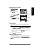
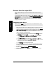
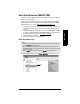
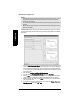
Table Of Contents
- Table of Contents
- SITRANS LR260 Overview
- Specifications
- Installation
- Wiring
- Quick Start via local operation
- Operating via SIMATIC PDM
- Parameter Reference
- Pull-down menus via SIMATIC PDM
- Quick Start Wizard
- 1. Quick Start
- 2. Setup
- 2.1. Device
- 2.2. Input
- 2.2.1. Sensor Calibration (SENSOR CALIB.)
- 2.2.1.1. Antenna
- 2.2.1.2. Sensor Units
- 2.2.1.3. Low Calibration Pt. (LOW CALIB. PT.)
- 2.2.1.4. High Calibration Pt. (HIGH CALIB. PT.)
- 2.2.1.5. Limit Sensor Value
- 2.2.1.6. Unit (Level)
- 2.2.1.7. Low Level Point
- 2.2.1.8. High Level Point
- 2.2.1.9. Level Offset
- 2.2.1.10. Sensor Offset
- 2.2.1.11. Temperature Units (TEMP UNITS)
- 2.2.3. Echo Processing (ECHO PROC)
- 2.2.4. TVT (Auto False Echo Suppression) setup
- 2.2.5. TVT Shaper
- 2.2.6. Rate
- 2.2.7. Transducer Block Values (for diagnostic purposes)
- 2.2.1. Sensor Calibration (SENSOR CALIB.)
- 2.3. Output
- 2.4. Fail-safe
- 3. Diagnostics
- 3.1. Fault Reset
- 3.2. Echo Profile
- 3.3. Measured Values (MEAS. VALUES)
- 3.3.1. Min. Measured Value (MIN. MEAS. VALUE)
- 3.3.2. Max. Measured Value (MAX. MEAS. VALUE)
- 3.3.3. Minimum Output Value - AIFB1 (MIN. OUTPUT FB1)
- 3.3.4. Maximum Output Value - AIFB1 (MAX. OUTPUT FB1)
- 3.3.5. Minimum Output Value - AIFB2 (MIN. OUTPUT FB2)
- 3.3.6. Maximum Output Value - AIFB2 (MAX. OUTPUT FB2)
- 3.3.7. Minimum Internal Temperature (MIN. INTERN. TEMP)
- 3.3.8. Maximum Internal Temperature (MAX. INTERN. TEMP)
- 3.4. Remaining Device Lifetime (REMAIN. DEV. LIFE)
- 3.4.1. Total Device Operating Time (TOTAL OP. TIME)
- 3.4.2. Remaining Device Lifetime (REMAIN LIFETIME)
- 3.4.3. Maintenance Required Limit (MAINT REQ LIMIT)
- 3.4.4. Maintenance Demanded Limit (MAINT DEM LIMIT)
- 3.4.5. Maintenance Alert Activation (ALERT ACTIVATION)
- 3.4.6. Total Expected Device Life (TOTAL EXP. LIFE)
- 3.4.7. Maintenance Status (MAINT STAT)
- 3.4.8. Acknowledge Status (ACK STATUS)
- 3.4.9. Acknowledge (ACK)
- 3.5. Remaining Sensor Lifetime (REMAIN SENS. LIFE)
- 3.5.1. Total Sensor Operating Time (SENS OP. TIME)
- 3.5.2. Remaining Sensor Lifetime (REMAIN LIFETIME)
- 3.5.3. Maintenance Required Limit (MAINT REQ LIMIT)
- 3.5.4. Maintenance Demanded Limit (MAINT. DEM. LIMIT)
- 3.5.5. Maintenance Alert Activation (ALERT ACTIVATION)
- 3.5.6. Total Expected Sensor Life (TOTAL EXP. LIFE)
- 3.5.7. Maintenance Status (MAINT STAT)
- 3.5.8. Acknowledge Status (ACK STATUS)
- 3.5.9. Acknowledge (ACK)
- 3.6. Condensed Status Setup (COND. STAT. SETUP)
- 3.7. Condensed Status
- 4. Service
- 4.1. Device Reset
- 4.2. LCD Fast Mode
- 4.3. LCD Contrast
- 4.4. PROFIBUS Ident Number (PROFIBUS IDENT)
- 4.5. Powered Hours
- 4.6. Power-on Resets
- 4.17. Service Interval
- 4.17.1. Time Last Serviced (TIME LAST SERV)
- 4.17.2. Remaining Lifetime (REMAIN LIFETIME)
- 4.17.3. Maintenance Required Limit (MAINT REQ LIMIT)
- 4.17.4. Maintenance Demanded Limit (MAINT DEM. LIMIT)
- 4.17.5. Alert Activation
- 4.17.6. Service Interval
- 4.17.7. Maintenance Status (MAINT STAT)
- 4.17.8. Acknowledge Status (ACK STATUS)
- 4.17.9. Acknowledge (ACK)
- 4.18. Calibration Interval (CALIB INTERVAL)
- 4.18.1. Time Last Calibrated (TIME LAST CAL.)
- 4.18.2. Remaining Lifetime (REMAIN LIFETIME)
- 4.18.3. Maintenance Required Limit (MAINT REQ LIMIT)
- 4.18.4. Maintenance Demanded Limit (MAINT DEM LIMIT)
- 4.18.5. Alert Activation
- 4.18.6. Total Calibration Interval (TOTAL CALIB. INTRV)
- 4.18.7. Maintenance Status (MAINT STAT)
- 4.18.8. Acknowledge Status (ACK STAT)
- 4.18.9. Acknowledge (ACK)
- 5. Communication
- 6. Security
- 7. Language
- Appendix A: Alphabetical Parameter List
- Appendix B: Troubleshooting
- Appendix C: Maintenance
- Appendix D: Technical Reference
- Appendix E: Application Example
- Appendix F: PROFIBUS PA Profile Structure
- Appendix G: Communications via PROFIBUS PA
- Appendix H: Firmware Revision History
- Glossary
- Index
- LCD menu structure

A5E32337685 SITRANS LR260 (PROFIBUS PA) – OPERATING INSTRUCTIONS Page 39
mmmmm
SIMATIC PDM
Quick Start Wizard via SIMATIC PDM
The graphic Quick Start Wizard provides an easy 4-step guide to help you configure the
device for a simple application.
Please consult the operating instructions or online help for details on using SIMATIC
PDM. (Application Guides for setting up Siemens PROFIBUS PA devices with SIMATIC
PDM are available on our website: www.siemens.com/processautomation
.)
1. If you have not already done so, check that you have the most up-to-date Electronic
Device Description (EDD) for your instrument. (See
Configuring a new device
on
page 38.)
2. Launch SIMATIC Manager and create a new project for LR260. Application Guides
for setting up PROFIBUS PA devices with SIMATIC PDM can be downloaded from
the product page of our website at: www.siemens.com/LR260
.
3. Upload parameters to the PC/PG.
4. Configure the device via the Quick Start Wizard.
Quick Start Wizard steps
Launch SIMATIC PDM, open the menu Device – Quick Start, and follow steps 1 to 4.
Notes:
• The Quick Start wizard settings are inter-related and changes apply only after you
click on Transfer at the end of step 4.
• Do not use the Quick Start Wizard to modify individual parameters: see instead
Parameter Reference
on page 51 (perform customization only after the Quick Start
has been completed).
• Click on BACK to return and revise setting or Cancel to exit the Quick Start.
Quick
Start