
User's Manual
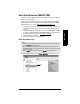
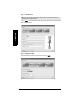
Table Of Contents
- Table of Contents
- SITRANS LR260 Overview
- Specifications
- Installation
- Wiring
- Quick Start via local operation
- Operating via SIMATIC PDM
- Parameter Reference
- Pull-down menus via SIMATIC PDM
- Quick Start Wizard
- 1. Quick Start
- 2. Setup
- 2.1. Device
- 2.2. Input
- 2.2.1. Sensor Calibration (SENSOR CALIB.)
- 2.2.1.1. Antenna
- 2.2.1.2. Sensor Units
- 2.2.1.3. Low Calibration Pt. (LOW CALIB. PT.)
- 2.2.1.4. High Calibration Pt. (HIGH CALIB. PT.)
- 2.2.1.5. Limit Sensor Value
- 2.2.1.6. Unit (Level)
- 2.2.1.7. Low Level Point
- 2.2.1.8. High Level Point
- 2.2.1.9. Level Offset
- 2.2.1.10. Sensor Offset
- 2.2.1.11. Temperature Units (TEMP UNITS)
- 2.2.3. Echo Processing (ECHO PROC)
- 2.2.4. TVT (Auto False Echo Suppression) setup
- 2.2.5. TVT Shaper
- 2.2.6. Rate
- 2.2.7. Transducer Block Values (for diagnostic purposes)
- 2.2.1. Sensor Calibration (SENSOR CALIB.)
- 2.3. Output
- 2.4. Fail-safe
- 3. Diagnostics
- 3.1. Fault Reset
- 3.2. Echo Profile
- 3.3. Measured Values (MEAS. VALUES)
- 3.3.1. Min. Measured Value (MIN. MEAS. VALUE)
- 3.3.2. Max. Measured Value (MAX. MEAS. VALUE)
- 3.3.3. Minimum Output Value - AIFB1 (MIN. OUTPUT FB1)
- 3.3.4. Maximum Output Value - AIFB1 (MAX. OUTPUT FB1)
- 3.3.5. Minimum Output Value - AIFB2 (MIN. OUTPUT FB2)
- 3.3.6. Maximum Output Value - AIFB2 (MAX. OUTPUT FB2)
- 3.3.7. Minimum Internal Temperature (MIN. INTERN. TEMP)
- 3.3.8. Maximum Internal Temperature (MAX. INTERN. TEMP)
- 3.4. Remaining Device Lifetime (REMAIN. DEV. LIFE)
- 3.4.1. Total Device Operating Time (TOTAL OP. TIME)
- 3.4.2. Remaining Device Lifetime (REMAIN LIFETIME)
- 3.4.3. Maintenance Required Limit (MAINT REQ LIMIT)
- 3.4.4. Maintenance Demanded Limit (MAINT DEM LIMIT)
- 3.4.5. Maintenance Alert Activation (ALERT ACTIVATION)
- 3.4.6. Total Expected Device Life (TOTAL EXP. LIFE)
- 3.4.7. Maintenance Status (MAINT STAT)
- 3.4.8. Acknowledge Status (ACK STATUS)
- 3.4.9. Acknowledge (ACK)
- 3.5. Remaining Sensor Lifetime (REMAIN SENS. LIFE)
- 3.5.1. Total Sensor Operating Time (SENS OP. TIME)
- 3.5.2. Remaining Sensor Lifetime (REMAIN LIFETIME)
- 3.5.3. Maintenance Required Limit (MAINT REQ LIMIT)
- 3.5.4. Maintenance Demanded Limit (MAINT. DEM. LIMIT)
- 3.5.5. Maintenance Alert Activation (ALERT ACTIVATION)
- 3.5.6. Total Expected Sensor Life (TOTAL EXP. LIFE)
- 3.5.7. Maintenance Status (MAINT STAT)
- 3.5.8. Acknowledge Status (ACK STATUS)
- 3.5.9. Acknowledge (ACK)
- 3.6. Condensed Status Setup (COND. STAT. SETUP)
- 3.7. Condensed Status
- 4. Service
- 4.1. Device Reset
- 4.2. LCD Fast Mode
- 4.3. LCD Contrast
- 4.4. PROFIBUS Ident Number (PROFIBUS IDENT)
- 4.5. Powered Hours
- 4.6. Power-on Resets
- 4.17. Service Interval
- 4.17.1. Time Last Serviced (TIME LAST SERV)
- 4.17.2. Remaining Lifetime (REMAIN LIFETIME)
- 4.17.3. Maintenance Required Limit (MAINT REQ LIMIT)
- 4.17.4. Maintenance Demanded Limit (MAINT DEM. LIMIT)
- 4.17.5. Alert Activation
- 4.17.6. Service Interval
- 4.17.7. Maintenance Status (MAINT STAT)
- 4.17.8. Acknowledge Status (ACK STATUS)
- 4.17.9. Acknowledge (ACK)
- 4.18. Calibration Interval (CALIB INTERVAL)
- 4.18.1. Time Last Calibrated (TIME LAST CAL.)
- 4.18.2. Remaining Lifetime (REMAIN LIFETIME)
- 4.18.3. Maintenance Required Limit (MAINT REQ LIMIT)
- 4.18.4. Maintenance Demanded Limit (MAINT DEM LIMIT)
- 4.18.5. Alert Activation
- 4.18.6. Total Calibration Interval (TOTAL CALIB. INTRV)
- 4.18.7. Maintenance Status (MAINT STAT)
- 4.18.8. Acknowledge Status (ACK STAT)
- 4.18.9. Acknowledge (ACK)
- 5. Communication
- 6. Security
- 7. Language
- Appendix A: Alphabetical Parameter List
- Appendix B: Troubleshooting
- Appendix C: Maintenance
- Appendix D: Technical Reference
- Appendix E: Application Example
- Appendix F: PROFIBUS PA Profile Structure
- Appendix G: Communications via PROFIBUS PA
- Appendix H: Firmware Revision History
- Glossary
- Index
- LCD menu structure

A5E32337685 SITRANS LR260 (PROFIBUS PA) – OPERATING INSTRUCTIONS Page 37
mmmmm
SIMATIC PDM
Operating via SIMATIC PDM
SIMATIC PDM is a software package used to commission and maintain SITRANS LR260 and
other process devices. Please consult the operating instructions or online help for details on
using SIMATIC PDM. (You can find more information at www.fielddevices.com
: go to Products
and Solutions > Products and Systems > Communications and Software > Process Device
Manager.)
Functions in SIMATIC PDM
SIMATIC PDM monitors the process values, alarms and status signals of the device. It allows
you to display, compare, adjust, verify, and simulate process device data.
For information on adjusting parameter values and viewing the results, see
Changing
parameter settings using SIMATIC PDM
on page 42 and
Parameters accessed via pull-down
menus
on page 42.
Features of SIMATIC PDM Rev. 6.0, SP3 (or higher)
The graphic interface in SITRANS LR260 makes monitoring and adjustments easy:
• The graphic Quick Start Wizard provides an easy 4-step guide to help you configure
the device for a simple application. See
Quick Start Wizard via SIMATIC PDM
on
page 39 for instructions.
•See
Display
on page 43 to monitor process variables.
•See
Echo profile
on page 43 for easy echo profile comparison.
•See
Trend
on page 46 for Level trend monitoring.
•See
Auto False Echo Suppression
on page 44 and
TVT Shaper
on page 45 on
adjusting the TVT curve to avoid false echoes.
•See
Simulation
on page 46 for simulating process values during commissioning/
maintenance.
Note: For a complete list of parameters with instructions, see
Parameter Reference
starting on page 51.
Note:
• While the device is in PROGRAM mode, the output remains active and continues to
respond to changes in the device.
• Do not use the handheld programmer at the same time as SIMATIC PDM, or erratic
operation may result.