
User's Manual
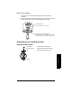
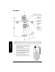
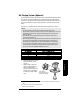
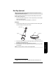

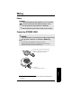
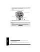
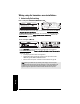
Table Of Contents
- Table of Contents
- SITRANS LR260 Overview
- Specifications
- Installation
- Wiring
- Quick Start via local operation
- Operating via SIMATIC PDM
- Parameter Reference
- Pull-down menus via SIMATIC PDM
- Quick Start Wizard
- 1. Quick Start
- 2. Setup
- 2.1. Device
- 2.2. Input
- 2.2.1. Sensor Calibration (SENSOR CALIB.)
- 2.2.1.1. Antenna
- 2.2.1.2. Sensor Units
- 2.2.1.3. Low Calibration Pt. (LOW CALIB. PT.)
- 2.2.1.4. High Calibration Pt. (HIGH CALIB. PT.)
- 2.2.1.5. Limit Sensor Value
- 2.2.1.6. Unit (Level)
- 2.2.1.7. Low Level Point
- 2.2.1.8. High Level Point
- 2.2.1.9. Level Offset
- 2.2.1.10. Sensor Offset
- 2.2.1.11. Temperature Units (TEMP UNITS)
- 2.2.3. Echo Processing (ECHO PROC)
- 2.2.4. TVT (Auto False Echo Suppression) setup
- 2.2.5. TVT Shaper
- 2.2.6. Rate
- 2.2.7. Transducer Block Values (for diagnostic purposes)
- 2.2.1. Sensor Calibration (SENSOR CALIB.)
- 2.3. Output
- 2.4. Fail-safe
- 3. Diagnostics
- 3.1. Fault Reset
- 3.2. Echo Profile
- 3.3. Measured Values (MEAS. VALUES)
- 3.3.1. Min. Measured Value (MIN. MEAS. VALUE)
- 3.3.2. Max. Measured Value (MAX. MEAS. VALUE)
- 3.3.3. Minimum Output Value - AIFB1 (MIN. OUTPUT FB1)
- 3.3.4. Maximum Output Value - AIFB1 (MAX. OUTPUT FB1)
- 3.3.5. Minimum Output Value - AIFB2 (MIN. OUTPUT FB2)
- 3.3.6. Maximum Output Value - AIFB2 (MAX. OUTPUT FB2)
- 3.3.7. Minimum Internal Temperature (MIN. INTERN. TEMP)
- 3.3.8. Maximum Internal Temperature (MAX. INTERN. TEMP)
- 3.4. Remaining Device Lifetime (REMAIN. DEV. LIFE)
- 3.4.1. Total Device Operating Time (TOTAL OP. TIME)
- 3.4.2. Remaining Device Lifetime (REMAIN LIFETIME)
- 3.4.3. Maintenance Required Limit (MAINT REQ LIMIT)
- 3.4.4. Maintenance Demanded Limit (MAINT DEM LIMIT)
- 3.4.5. Maintenance Alert Activation (ALERT ACTIVATION)
- 3.4.6. Total Expected Device Life (TOTAL EXP. LIFE)
- 3.4.7. Maintenance Status (MAINT STAT)
- 3.4.8. Acknowledge Status (ACK STATUS)
- 3.4.9. Acknowledge (ACK)
- 3.5. Remaining Sensor Lifetime (REMAIN SENS. LIFE)
- 3.5.1. Total Sensor Operating Time (SENS OP. TIME)
- 3.5.2. Remaining Sensor Lifetime (REMAIN LIFETIME)
- 3.5.3. Maintenance Required Limit (MAINT REQ LIMIT)
- 3.5.4. Maintenance Demanded Limit (MAINT. DEM. LIMIT)
- 3.5.5. Maintenance Alert Activation (ALERT ACTIVATION)
- 3.5.6. Total Expected Sensor Life (TOTAL EXP. LIFE)
- 3.5.7. Maintenance Status (MAINT STAT)
- 3.5.8. Acknowledge Status (ACK STATUS)
- 3.5.9. Acknowledge (ACK)
- 3.6. Condensed Status Setup (COND. STAT. SETUP)
- 3.7. Condensed Status
- 4. Service
- 4.1. Device Reset
- 4.2. LCD Fast Mode
- 4.3. LCD Contrast
- 4.4. PROFIBUS Ident Number (PROFIBUS IDENT)
- 4.5. Powered Hours
- 4.6. Power-on Resets
- 4.17. Service Interval
- 4.17.1. Time Last Serviced (TIME LAST SERV)
- 4.17.2. Remaining Lifetime (REMAIN LIFETIME)
- 4.17.3. Maintenance Required Limit (MAINT REQ LIMIT)
- 4.17.4. Maintenance Demanded Limit (MAINT DEM. LIMIT)
- 4.17.5. Alert Activation
- 4.17.6. Service Interval
- 4.17.7. Maintenance Status (MAINT STAT)
- 4.17.8. Acknowledge Status (ACK STATUS)
- 4.17.9. Acknowledge (ACK)
- 4.18. Calibration Interval (CALIB INTERVAL)
- 4.18.1. Time Last Calibrated (TIME LAST CAL.)
- 4.18.2. Remaining Lifetime (REMAIN LIFETIME)
- 4.18.3. Maintenance Required Limit (MAINT REQ LIMIT)
- 4.18.4. Maintenance Demanded Limit (MAINT DEM LIMIT)
- 4.18.5. Alert Activation
- 4.18.6. Total Calibration Interval (TOTAL CALIB. INTRV)
- 4.18.7. Maintenance Status (MAINT STAT)
- 4.18.8. Acknowledge Status (ACK STAT)
- 4.18.9. Acknowledge (ACK)
- 5. Communication
- 6. Security
- 7. Language
- Appendix A: Alphabetical Parameter List
- Appendix B: Troubleshooting
- Appendix C: Maintenance
- Appendix D: Technical Reference
- Appendix E: Application Example
- Appendix F: PROFIBUS PA Profile Structure
- Appendix G: Communications via PROFIBUS PA
- Appendix H: Firmware Revision History
- Glossary
- Index
- LCD menu structure

Page 24 SITRANS LR260 (PROFIBUS PA) – OPERATING INSTRUCTIONS A5E32337685
mmmmm
Wiring
Wiring setup for hazardous area installations
1. Intrinsically Safe wiring
• For wiring requirements: follow local regulations.
• Approved dust-tight and water-tight conduit seals are required for outdoor
NEMA 4X / type 4X / NEMA 6, IP67, IP68 locations.
• Refer to
Instructions specific to hazardous area installations
on page 26.
Note: Selecting a suitable PLC input module, power supply, or barrier requires
knowledge about Intrinsic Safety and the application. It is the responsibility of the
installer to ensure that the intrinsically safe installation complies with both the
apparatus approval requirements and the relevant national code of practice.
SITRANS LR260
Siemens Milltronics Process Instruments, Peterborough
7MLxxxx-xxxxx-xxxx
Encl.: NEMA / TYPE 4X, 6, IP67, IP68
Amb.Temp.: – 40°C to 80°C
Power Rating: 30 V
Max., 15 mA
Serial No: GYZ / A1034567
FISCO:
Field Device
Ui = 17.5 V
Ii = 380 mA
Pi = 5.32 W
Ci = 0
Li = 0
Entity:
Ui=24V
Ii = 250 mA
Pi = 1.2 W
Ci = 0
Li = 0
0518
0891
Assembled in Canada with domestic and imported parts
PROFIBUS PA
KCC-REM-S49
SITRANSLR
II 1 G D, 1/2 D, 2 D
Ex ia IIC T4 Ga
Ex ta IIIC T100°C Da
SIRA 11ATEX2348X
IECEx SIR 11.0153X
ARP0108 Ex ia IIC T4 Ga
ATENÇÃO - RISCO POTENCIAL DE CARGA ELETROSTÁTICA – VEJA INSTRUÇÕES
- UTILIZAR CABOS ADEQUADOS PARA TEMPERATURAS >100 °C
WARNING: Use Cable Rated >100°C
Ex ia IIC T4 Ga
Ex ta IIIC T100°C Da
DNV 12.0081 X
OCP 0017
The ATEX certificate listed on the nameplate
can be downloaded from the product page of our website at: www.siemens.com/LR260. Go
to Support > Approvals / Certificates.
The IECEx certificate listed on the nameplate can be viewed on the IECEx website. Go to:
http://iecex.iec.ch
and click on Ex Equipment Certificates of Conformity then enter the
certificate number IECEx SIR 11.0153X.
Device nameplate (ATEX/IECEX/INMETRO/C-TICK)
FM/CSA Intrinsically Safe connection drawing
number A5E03745619 can be downloaded from the product page of our website at:
www.siemens.com/LR260
. Go to Support > Installation Drawings > Level Measurement >
Continuous - Radar.
Device nameplate (FM/CSA)