
User's Manual
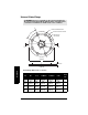
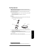

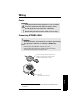
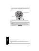
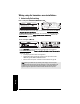
Table Of Contents
- Table of Contents
- SITRANS LR260 Overview
- Specifications
- Installation
- Wiring
- Quick Start via local operation
- Operating via SIMATIC PDM
- Parameter Reference
- Pull-down menus via SIMATIC PDM
- Quick Start Wizard
- 1. Quick Start
- 2. Setup
- 2.1. Device
- 2.2. Input
- 2.2.1. Sensor Calibration (SENSOR CALIB.)
- 2.2.1.1. Antenna
- 2.2.1.2. Sensor Units
- 2.2.1.3. Low Calibration Pt. (LOW CALIB. PT.)
- 2.2.1.4. High Calibration Pt. (HIGH CALIB. PT.)
- 2.2.1.5. Limit Sensor Value
- 2.2.1.6. Unit (Level)
- 2.2.1.7. Low Level Point
- 2.2.1.8. High Level Point
- 2.2.1.9. Level Offset
- 2.2.1.10. Sensor Offset
- 2.2.1.11. Temperature Units (TEMP UNITS)
- 2.2.3. Echo Processing (ECHO PROC)
- 2.2.4. TVT (Auto False Echo Suppression) setup
- 2.2.5. TVT Shaper
- 2.2.6. Rate
- 2.2.7. Transducer Block Values (for diagnostic purposes)
- 2.2.1. Sensor Calibration (SENSOR CALIB.)
- 2.3. Output
- 2.4. Fail-safe
- 3. Diagnostics
- 3.1. Fault Reset
- 3.2. Echo Profile
- 3.3. Measured Values (MEAS. VALUES)
- 3.3.1. Min. Measured Value (MIN. MEAS. VALUE)
- 3.3.2. Max. Measured Value (MAX. MEAS. VALUE)
- 3.3.3. Minimum Output Value - AIFB1 (MIN. OUTPUT FB1)
- 3.3.4. Maximum Output Value - AIFB1 (MAX. OUTPUT FB1)
- 3.3.5. Minimum Output Value - AIFB2 (MIN. OUTPUT FB2)
- 3.3.6. Maximum Output Value - AIFB2 (MAX. OUTPUT FB2)
- 3.3.7. Minimum Internal Temperature (MIN. INTERN. TEMP)
- 3.3.8. Maximum Internal Temperature (MAX. INTERN. TEMP)
- 3.4. Remaining Device Lifetime (REMAIN. DEV. LIFE)
- 3.4.1. Total Device Operating Time (TOTAL OP. TIME)
- 3.4.2. Remaining Device Lifetime (REMAIN LIFETIME)
- 3.4.3. Maintenance Required Limit (MAINT REQ LIMIT)
- 3.4.4. Maintenance Demanded Limit (MAINT DEM LIMIT)
- 3.4.5. Maintenance Alert Activation (ALERT ACTIVATION)
- 3.4.6. Total Expected Device Life (TOTAL EXP. LIFE)
- 3.4.7. Maintenance Status (MAINT STAT)
- 3.4.8. Acknowledge Status (ACK STATUS)
- 3.4.9. Acknowledge (ACK)
- 3.5. Remaining Sensor Lifetime (REMAIN SENS. LIFE)
- 3.5.1. Total Sensor Operating Time (SENS OP. TIME)
- 3.5.2. Remaining Sensor Lifetime (REMAIN LIFETIME)
- 3.5.3. Maintenance Required Limit (MAINT REQ LIMIT)
- 3.5.4. Maintenance Demanded Limit (MAINT. DEM. LIMIT)
- 3.5.5. Maintenance Alert Activation (ALERT ACTIVATION)
- 3.5.6. Total Expected Sensor Life (TOTAL EXP. LIFE)
- 3.5.7. Maintenance Status (MAINT STAT)
- 3.5.8. Acknowledge Status (ACK STATUS)
- 3.5.9. Acknowledge (ACK)
- 3.6. Condensed Status Setup (COND. STAT. SETUP)
- 3.7. Condensed Status
- 4. Service
- 4.1. Device Reset
- 4.2. LCD Fast Mode
- 4.3. LCD Contrast
- 4.4. PROFIBUS Ident Number (PROFIBUS IDENT)
- 4.5. Powered Hours
- 4.6. Power-on Resets
- 4.17. Service Interval
- 4.17.1. Time Last Serviced (TIME LAST SERV)
- 4.17.2. Remaining Lifetime (REMAIN LIFETIME)
- 4.17.3. Maintenance Required Limit (MAINT REQ LIMIT)
- 4.17.4. Maintenance Demanded Limit (MAINT DEM. LIMIT)
- 4.17.5. Alert Activation
- 4.17.6. Service Interval
- 4.17.7. Maintenance Status (MAINT STAT)
- 4.17.8. Acknowledge Status (ACK STATUS)
- 4.17.9. Acknowledge (ACK)
- 4.18. Calibration Interval (CALIB INTERVAL)
- 4.18.1. Time Last Calibrated (TIME LAST CAL.)
- 4.18.2. Remaining Lifetime (REMAIN LIFETIME)
- 4.18.3. Maintenance Required Limit (MAINT REQ LIMIT)
- 4.18.4. Maintenance Demanded Limit (MAINT DEM LIMIT)
- 4.18.5. Alert Activation
- 4.18.6. Total Calibration Interval (TOTAL CALIB. INTRV)
- 4.18.7. Maintenance Status (MAINT STAT)
- 4.18.8. Acknowledge Status (ACK STAT)
- 4.18.9. Acknowledge (ACK)
- 5. Communication
- 6. Security
- 7. Language
- Appendix A: Alphabetical Parameter List
- Appendix B: Troubleshooting
- Appendix C: Maintenance
- Appendix D: Technical Reference
- Appendix E: Application Example
- Appendix F: PROFIBUS PA Profile Structure
- Appendix G: Communications via PROFIBUS PA
- Appendix H: Firmware Revision History
- Glossary
- Index
- LCD menu structure

Page 18 SITRANS LR260 (PROFIBUS PA) – OPERATING INSTRUCTIONS A5E32337685
mmmmm
Installation
Universal Slotted Flange
Slotted Flange Dimensions (see above)
1)
WARNING: The user is responsible for the selection of bolting and
gasket materials which will fall within the limits of the flange and its
intended use and which are suitable for the service conditions.
Pipe
Size
Flange
O.D.
Thick-
ness (s)
Bolt Hole
Circle Max Ø
Bolt Hole
Circle Min Ø
Bolt Hole
radius
No. of
Slotted
Holes
2" or
50 mm
6.50"
(165 mm)
0.38"
(9.65 mm)
4.92"
(125 mm)
4.72"
(120 mm)
0.38"
(9.65 mm)
4
3" or
80 mm
7.87"
(200 mm)
0.38"
(9.65 mm)
6.30"
(160 mm)
5.91"
(150 mm)
0.38"
(9.65 mm)
8
4" or
100 mm
9.00"
(229 mm)
0.38"
(9.65 mm)
7.52"
(191 mm)
6.89"
(175 mm)
0.38"
(9.65 mm)
8
6" or
150 mm
11.22"
(285 mm)
0.38"
(9.65 mm)
9.53"
(242 mm)
9.45"
(240 mm)
0.45"
(11.5 mm)
8
flange O.D.
bolt hole circle
min. diameter
number of slotted bolt holes
section A-A
thickness
bolt hole circle max. diameter