
User's Manual


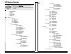
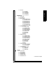

Table Of Contents
- Table of Contents
- SITRANS LR260 Overview
- Specifications
- Installation
- Wiring
- Quick Start via local operation
- Operating via SIMATIC PDM
- Parameter Reference
- Pull-down menus via SIMATIC PDM
- Quick Start Wizard
- 1. Quick Start
- 2. Setup
- 2.1. Device
- 2.2. Input
- 2.2.1. Sensor Calibration (SENSOR CALIB.)
- 2.2.1.1. Antenna
- 2.2.1.2. Sensor Units
- 2.2.1.3. Low Calibration Pt. (LOW CALIB. PT.)
- 2.2.1.4. High Calibration Pt. (HIGH CALIB. PT.)
- 2.2.1.5. Limit Sensor Value
- 2.2.1.6. Unit (Level)
- 2.2.1.7. Low Level Point
- 2.2.1.8. High Level Point
- 2.2.1.9. Level Offset
- 2.2.1.10. Sensor Offset
- 2.2.1.11. Temperature Units (TEMP UNITS)
- 2.2.3. Echo Processing (ECHO PROC)
- 2.2.4. TVT (Auto False Echo Suppression) setup
- 2.2.5. TVT Shaper
- 2.2.6. Rate
- 2.2.7. Transducer Block Values (for diagnostic purposes)
- 2.2.1. Sensor Calibration (SENSOR CALIB.)
- 2.3. Output
- 2.4. Fail-safe
- 3. Diagnostics
- 3.1. Fault Reset
- 3.2. Echo Profile
- 3.3. Measured Values (MEAS. VALUES)
- 3.3.1. Min. Measured Value (MIN. MEAS. VALUE)
- 3.3.2. Max. Measured Value (MAX. MEAS. VALUE)
- 3.3.3. Minimum Output Value - AIFB1 (MIN. OUTPUT FB1)
- 3.3.4. Maximum Output Value - AIFB1 (MAX. OUTPUT FB1)
- 3.3.5. Minimum Output Value - AIFB2 (MIN. OUTPUT FB2)
- 3.3.6. Maximum Output Value - AIFB2 (MAX. OUTPUT FB2)
- 3.3.7. Minimum Internal Temperature (MIN. INTERN. TEMP)
- 3.3.8. Maximum Internal Temperature (MAX. INTERN. TEMP)
- 3.4. Remaining Device Lifetime (REMAIN. DEV. LIFE)
- 3.4.1. Total Device Operating Time (TOTAL OP. TIME)
- 3.4.2. Remaining Device Lifetime (REMAIN LIFETIME)
- 3.4.3. Maintenance Required Limit (MAINT REQ LIMIT)
- 3.4.4. Maintenance Demanded Limit (MAINT DEM LIMIT)
- 3.4.5. Maintenance Alert Activation (ALERT ACTIVATION)
- 3.4.6. Total Expected Device Life (TOTAL EXP. LIFE)
- 3.4.7. Maintenance Status (MAINT STAT)
- 3.4.8. Acknowledge Status (ACK STATUS)
- 3.4.9. Acknowledge (ACK)
- 3.5. Remaining Sensor Lifetime (REMAIN SENS. LIFE)
- 3.5.1. Total Sensor Operating Time (SENS OP. TIME)
- 3.5.2. Remaining Sensor Lifetime (REMAIN LIFETIME)
- 3.5.3. Maintenance Required Limit (MAINT REQ LIMIT)
- 3.5.4. Maintenance Demanded Limit (MAINT. DEM. LIMIT)
- 3.5.5. Maintenance Alert Activation (ALERT ACTIVATION)
- 3.5.6. Total Expected Sensor Life (TOTAL EXP. LIFE)
- 3.5.7. Maintenance Status (MAINT STAT)
- 3.5.8. Acknowledge Status (ACK STATUS)
- 3.5.9. Acknowledge (ACK)
- 3.6. Condensed Status Setup (COND. STAT. SETUP)
- 3.7. Condensed Status
- 4. Service
- 4.1. Device Reset
- 4.2. LCD Fast Mode
- 4.3. LCD Contrast
- 4.4. PROFIBUS Ident Number (PROFIBUS IDENT)
- 4.5. Powered Hours
- 4.6. Power-on Resets
- 4.17. Service Interval
- 4.17.1. Time Last Serviced (TIME LAST SERV)
- 4.17.2. Remaining Lifetime (REMAIN LIFETIME)
- 4.17.3. Maintenance Required Limit (MAINT REQ LIMIT)
- 4.17.4. Maintenance Demanded Limit (MAINT DEM. LIMIT)
- 4.17.5. Alert Activation
- 4.17.6. Service Interval
- 4.17.7. Maintenance Status (MAINT STAT)
- 4.17.8. Acknowledge Status (ACK STATUS)
- 4.17.9. Acknowledge (ACK)
- 4.18. Calibration Interval (CALIB INTERVAL)
- 4.18.1. Time Last Calibrated (TIME LAST CAL.)
- 4.18.2. Remaining Lifetime (REMAIN LIFETIME)
- 4.18.3. Maintenance Required Limit (MAINT REQ LIMIT)
- 4.18.4. Maintenance Demanded Limit (MAINT DEM LIMIT)
- 4.18.5. Alert Activation
- 4.18.6. Total Calibration Interval (TOTAL CALIB. INTRV)
- 4.18.7. Maintenance Status (MAINT STAT)
- 4.18.8. Acknowledge Status (ACK STAT)
- 4.18.9. Acknowledge (ACK)
- 5. Communication
- 6. Security
- 7. Language
- Appendix A: Alphabetical Parameter List
- Appendix B: Troubleshooting
- Appendix C: Maintenance
- Appendix D: Technical Reference
- Appendix E: Application Example
- Appendix F: PROFIBUS PA Profile Structure
- Appendix G: Communications via PROFIBUS PA
- Appendix H: Firmware Revision History
- Glossary
- Index
- LCD menu structure

Page 142 SITRANS LR260 (PROFIBUS PA) – OPERATING INSTRUCTIONS SITRANS LR260 (PROFIBUS PA) – OPERATING INSTRUCTIONS A5E32337685
Appendix C: menu chart
LCD menu structure
1. QUICK START
1.1 APPLICATION TYPE
1.2 RESPONSE RATE
1.3 UNITS
1.4 OPERATION
1.5 LOW CALIB. PT.
1.6 HIGH CALIB. PT.
1.7 APPLY?
2. SETUP
2.1 DEVICE
2.1.1 TAG
2.1.2 DESCRIPTION
2.1.3 MESSAGE
2.1.4 FIRMWARE REV
2.1.5 LOADER REV
2.1.6 HARDWARE REV
2.2 INPUT
2.2.1 SENSOR CALIB.
2.2.1.1 ANTENNA
2.2.1.2 SENSOR UNITS
2.2.1.3 LOW CALIB. PT.
2.2.1.4 HIGH CALIB. PT.
2.2.1.5 LIMIT SENSOR VALUE
2.2.1.6 UNIT (LEVEL)
2.2.1.7 LOW LEVEL POINT
2.2.1.8 HIGH LEVEL POINT
2.2.1.9 LEVEL OFFSET
2.2.1.10 SENSOR OFFSET
2.2.1.11 TEMP UNITS
2.2.3 ECHO PROC.
2.2.3.1 ECHO SELECT
2.2.3.1.1 ALGORITHM
2.2.3.1.2 ECHO THRESHOLD
2.2.3.1.3 POSITION
2.2.3.1.4 ECHO MARKER
2.2.3.2 SAMPLING
2.2.3.2.1 ECHO LOCK
2.2.3.2.2 UP SAMP
2.2.3.2.3 DOWN SAMP
2.2.3.2.4 WINDOW
2.2.3.3 FILTERING
2.2.3.3.1 SHOTS
2.2.3.3.2 NARROW ECHO FIL.
2.2.3.3.3 REFORM ECHO
2.2.3.5 RANGE
2.2.3.5.1 NEAR RANGE
2.2.3.5.2 FAR RANGE
2.2.3.5.3 MIN SENSOR VAL
2.2.3.5.4 MAX SENSOR VAL
2.2.3.6 NOISE
2.0.0.0.1 CONFIDENCE
2.0.0.0.2 STRENGTH
2.2.4 TVT SETUP
2.2.4.1 TVT TYPE
2.2.4.2 TVT HOVER LEVEL
2.2.4.3 AUTO ECHO SUPP
2.2.4.4 AUTO SUPP RANGE
2.2.4.5 SHAPER MODE
2.2.5 TVT SHAPER
2.2.5.1 SHAPER 1-9
2.2.5.2 SHAPER 10-18
2.2.5.3 SHAPER 19-27
2.2.5.4 SHAPER 28-36
2.2.5.5 SHAPER 37-40
2.2.6 RATE
2.2.6.1 RESPONSE RATE
2.2.6.2 FILL RATE /MIN
2.2.6.3 EMPTY RATE /MIN
2.2.7 TB VALUES
2.2.7.1 MAIN OUTPUT
2.2.7.2 O/P NO LINEAR.
2.2.7.3 O/P NO OFFSETS
2.3 OUTPUT
2.3.1 AIFB 1
2.3.1.1 TARGET MODE
2.3.1.2 LABEL
2.3.1.3 UNIT
2.3.1.4 FILTER TIME CONS
2.3.1.5 CHANNEL
2.3.1.6 BATCH INFO
2.3.1.6.1 BATCH ID
2.3.1.6.2 BATCH UNIT
2.3.1.6.3 BATCH OPERATION
2.3.1.6.4 BATCH PHASE
2.3.1.7 PROC VALUE SCAL.
2.3.1.7.1 LOWER VALUE
2.3.1.7.2 UPPER VALUE
2.3.1.8 OUTPUT SCALE
2.3.1.8.1 LOWER VALUE
2.3.1.8.2 UPPER VALUE
2.3.1.9 OUTPUT LIMITS
2.3.1.9.1 LO LIMIT ALARM
2.3.1.9.2 LO LIMIT WARN
2.3.1.9.3 HI LIMIT WARN
2.3.1.9.4 HI LIMIT ALARM
2.3.1.9.5 LIMIT HYSTERESI.
2.3.1.10 HUMAN INTERFAC
2.3.1.10.1 DECIMAL POINT
2.3.2 AIFB 2 (AS AIFB 1)
Notes:
• In Navigation mode ARROW keys navigate the menu in the
direction of the arrow..
• See
Parameter Reference
on page 46 for detailed information and
instructions.
2. SETUP (cont’d)