
User's Manual
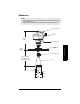
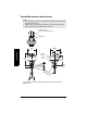
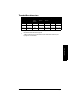

Table Of Contents
- Table of Contents
- SITRANS LR260 Overview
- Specifications
- Installation
- Wiring
- Quick Start via local operation
- Operating via SIMATIC PDM
- Parameter Reference
- Pull-down menus via SIMATIC PDM
- Quick Start Wizard
- 1. Quick Start
- 2. Setup
- 2.1. Device
- 2.2. Input
- 2.2.1. Sensor Calibration (SENSOR CALIB.)
- 2.2.1.1. Antenna
- 2.2.1.2. Sensor Units
- 2.2.1.3. Low Calibration Pt. (LOW CALIB. PT.)
- 2.2.1.4. High Calibration Pt. (HIGH CALIB. PT.)
- 2.2.1.5. Limit Sensor Value
- 2.2.1.6. Unit (Level)
- 2.2.1.7. Low Level Point
- 2.2.1.8. High Level Point
- 2.2.1.9. Level Offset
- 2.2.1.10. Sensor Offset
- 2.2.1.11. Temperature Units (TEMP UNITS)
- 2.2.3. Echo Processing (ECHO PROC)
- 2.2.4. TVT (Auto False Echo Suppression) setup
- 2.2.5. TVT Shaper
- 2.2.6. Rate
- 2.2.7. Transducer Block Values (for diagnostic purposes)
- 2.2.1. Sensor Calibration (SENSOR CALIB.)
- 2.3. Output
- 2.4. Fail-safe
- 3. Diagnostics
- 3.1. Fault Reset
- 3.2. Echo Profile
- 3.3. Measured Values (MEAS. VALUES)
- 3.3.1. Min. Measured Value (MIN. MEAS. VALUE)
- 3.3.2. Max. Measured Value (MAX. MEAS. VALUE)
- 3.3.3. Minimum Output Value - AIFB1 (MIN. OUTPUT FB1)
- 3.3.4. Maximum Output Value - AIFB1 (MAX. OUTPUT FB1)
- 3.3.5. Minimum Output Value - AIFB2 (MIN. OUTPUT FB2)
- 3.3.6. Maximum Output Value - AIFB2 (MAX. OUTPUT FB2)
- 3.3.7. Minimum Internal Temperature (MIN. INTERN. TEMP)
- 3.3.8. Maximum Internal Temperature (MAX. INTERN. TEMP)
- 3.4. Remaining Device Lifetime (REMAIN. DEV. LIFE)
- 3.4.1. Total Device Operating Time (TOTAL OP. TIME)
- 3.4.2. Remaining Device Lifetime (REMAIN LIFETIME)
- 3.4.3. Maintenance Required Limit (MAINT REQ LIMIT)
- 3.4.4. Maintenance Demanded Limit (MAINT DEM LIMIT)
- 3.4.5. Maintenance Alert Activation (ALERT ACTIVATION)
- 3.4.6. Total Expected Device Life (TOTAL EXP. LIFE)
- 3.4.7. Maintenance Status (MAINT STAT)
- 3.4.8. Acknowledge Status (ACK STATUS)
- 3.4.9. Acknowledge (ACK)
- 3.5. Remaining Sensor Lifetime (REMAIN SENS. LIFE)
- 3.5.1. Total Sensor Operating Time (SENS OP. TIME)
- 3.5.2. Remaining Sensor Lifetime (REMAIN LIFETIME)
- 3.5.3. Maintenance Required Limit (MAINT REQ LIMIT)
- 3.5.4. Maintenance Demanded Limit (MAINT. DEM. LIMIT)
- 3.5.5. Maintenance Alert Activation (ALERT ACTIVATION)
- 3.5.6. Total Expected Sensor Life (TOTAL EXP. LIFE)
- 3.5.7. Maintenance Status (MAINT STAT)
- 3.5.8. Acknowledge Status (ACK STATUS)
- 3.5.9. Acknowledge (ACK)
- 3.6. Condensed Status Setup (COND. STAT. SETUP)
- 3.7. Condensed Status
- 4. Service
- 4.1. Device Reset
- 4.2. LCD Fast Mode
- 4.3. LCD Contrast
- 4.4. PROFIBUS Ident Number (PROFIBUS IDENT)
- 4.5. Powered Hours
- 4.6. Power-on Resets
- 4.17. Service Interval
- 4.17.1. Time Last Serviced (TIME LAST SERV)
- 4.17.2. Remaining Lifetime (REMAIN LIFETIME)
- 4.17.3. Maintenance Required Limit (MAINT REQ LIMIT)
- 4.17.4. Maintenance Demanded Limit (MAINT DEM. LIMIT)
- 4.17.5. Alert Activation
- 4.17.6. Service Interval
- 4.17.7. Maintenance Status (MAINT STAT)
- 4.17.8. Acknowledge Status (ACK STATUS)
- 4.17.9. Acknowledge (ACK)
- 4.18. Calibration Interval (CALIB INTERVAL)
- 4.18.1. Time Last Calibrated (TIME LAST CAL.)
- 4.18.2. Remaining Lifetime (REMAIN LIFETIME)
- 4.18.3. Maintenance Required Limit (MAINT REQ LIMIT)
- 4.18.4. Maintenance Demanded Limit (MAINT DEM LIMIT)
- 4.18.5. Alert Activation
- 4.18.6. Total Calibration Interval (TOTAL CALIB. INTRV)
- 4.18.7. Maintenance Status (MAINT STAT)
- 4.18.8. Acknowledge Status (ACK STAT)
- 4.18.9. Acknowledge (ACK)
- 5. Communication
- 6. Security
- 7. Language
- Appendix A: Alphabetical Parameter List
- Appendix B: Troubleshooting
- Appendix C: Maintenance
- Appendix D: Technical Reference
- Appendix E: Application Example
- Appendix F: PROFIBUS PA Profile Structure
- Appendix G: Communications via PROFIBUS PA
- Appendix H: Firmware Revision History
- Glossary
- Index
- LCD menu structure

A5E32337685 SITRANS LR260 (PROFIBUS PA) – OPERATING INSTRUCTIONS Page 7
mmmmm
Specifications
Mechanical (Threaded Connection model)
• threaded connection 2" NPT (ASME B1.20.1), R (BSPT, EN 10226-1) or
G (BSPP, EN ISO 228-1)
materials 316L /1.4404 or 316L /1.4435 stainless steel
PTFE emitter
Environmental
• location indoor/ outdoor
• altitude 2000 m (6562 ft) max.
• ambient temperature 40 to +80 °C (40 to +176 °F)
• relative humidity suitable for outdoor
Type 4X/NEMA 4X, Type 6/NEMA 6, IP67 enclosure
(see note below)
• installation category I
• pollution degree 4
Process
•temperature
1)
-40 to +200 °C (-40 to +392 °F)
2)
(at process connection with FKM O-ring)
• pressure (vessel)
1
Refer to
Process Pressure/Temperature derating curves
on
page 108.
Approvals
•General CSA
US/C
, FM, CE
• Radio Europe (R&TTE), FCC, Industry Canada
• Hazardous ATEX II 1GD, 1/2D, 2D Ex ia IIC T4 Ga, Ex ta IIIC T100 °C Da
ATEX II 3G Ex nA IIC T4 Gc
IECEx SIR 11.0153X Ex ia IIC T4 Ga, Ex ta IIIC T100 °C Da
FM/CSA Class I, Div. 1, Groups A, B, C, D, Class II, Div. 1,
Groups E, F, G, Class III T4
FM/CSA Class I, Div 2, Groups A, B, C, D T5
SABS ARP0108 Ex ia IIC T4 Ga
Notes:
• Check
Approvals
on page 7, for the specific configuration you are about to use or
install.
• Use appropriate conduit seals to maintain IP or NEMA rating.
1)
The maximum temperature is dependent on the ambient temperature and vessel
pressure. For more detail, or for other configurations, see
Process Pressure/
Temperature derating curves
on page 108.
2)
Pressure rated version for maximum process temperature of 80 °C (176 °F)
Note: The device nameplate lists the approvals that apply to your device.