Radar Transmitters SITRANS LR260 (PROFIBUS PA) Operating Instructions 12/2013 SITRANS
Safety Guidelines: Warning notices must be observed to ensure personal safety as well as that of others, and to protect the product and the connected equipment. These warning notices are accompanied by a clarification of the level of caution to be observed. Qualified Personnel: This device/system may only be set up and operated in conjunction with this manual. Qualified personnel are only authorized to install and operate this equipment in accordance with established safety practices and standards.
Table of Contents SITRANS LR260 Overview ................................................................................................. 4 Specifications ...................................................................................................................... 5 Dimensions ...............................................................................................................................................9 Threaded Horn Antenna with extension .........................................
Table of Cotents mmmmm Configuring a new device .........................................................................................................38 Quick Start Wizard via SIMATIC PDM .............................................................................................39 Changing parameter settings using SIMATIC PDM ...........................................................42 Parameter Reference ..............................................................................................
Flour in steel storage vessel, level measurement .............................................................111 Appendix F: PROFIBUS PA Profile Structure ............................................................. 113 PROFIBUS Level Device Design ......................................................................................................113 Description of the blocks .........................................................................................................
Table of Cotents mmmmm Appendix H: Firmware Revision History .................................................................... 133 Glossary ............................................................................................................................ 135 Index .................................................................................................................................. 139 LCD menu structure ..............................................................................
Safety Notes Special attention must be paid to warnings and notes highlighted from the rest of the text by grey boxes.1) WARNING: relates to a caution symbol on the product, and means that failure to observe the necessary precautions can result in death, serious injury, and/or considerable material damage. WARNING1: means that failure to observe the necessary precautions can result in death, serious injury, and/or considerable material damage.
The Manual Notes: • Please follow the installation and operating procedures for a quick, trouble-free installation and to ensure the maximum accuracy and reliability of your SITRANS LR260. • This manual applies to the SITRANS LR260 (PROFIBUS PA) only. SITRANS LR260 mmmmm This manual will help you set up your SITRANS LR260 for optimum performance. We always welcome suggestions and comments about manual content, design, and accessibility. Please direct your comments to techpubs.smpi@siemens.com.
Abbreviations and Identifications Long Form A/D Analog to digital AIFB Analog Input Function Block CE / FM / CSA Conformitè Europèene / Factory Mutual / Canadian Standards Association Ci Internal capacitance D/A Digital to analog Digital Analog Converter DCS Distributed Control System dK dielectric constant Ii Input current Units safety approval F control room apparatus mA Io Output current IS Intrinsically Safe Li Internal inductance LTB Level Transducer Block mH milliHenry 10
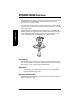
SITRANS LR260 Overview SITRANS LR260 is a 2-wire 25 GHz pulse radar level transmitter for continuous monitoring of solids and liquids in storage vessels including extreme levels of dust and high temperatures, to a range of 30 m (98.4 ft). SITRANS LR260 mmmmm The instrument consists of an electronic component coupled to a horn antenna with an integral Easy Aimer and flange for quick and easy positioning. A dust cover or air purging are available as options.
Specifications Notes: • Siemens Milltronics makes every attempt to ensure the accuracy of these specifications but reserves the right to change them at any time. Power Bus powered Current consumed Per IEC 61158-2 (PROFIBUS PA) 15.0 mA (General Purpose or Intrinsically Safe version) Performance Reference operating conditions according to IEC 60770-1 • ambient temperature +15 to +25 °C (+59 to +77 °F) • humidity 45% to 75% relative humidity • liquids K-band (25 GHz nominal) 2" horn: 10 m (32.
Dielectric constant of material measured • Minimum dK = 1.6 (depending on antenna and application type) Memory • non-volatile EEPROM • no battery required.
Mechanical (Threaded Connection model) • threaded connection materials 2" NPT (ASME B1.20.1), R (BSPT, EN 10226-1) or G (BSPP, EN ISO 228-1) 316L /1.4404 or 316L /1.4435 stainless steel PTFE emitter Environmental • • • • location altitude ambient temperature relative humidity • installation category indoor/ outdoor 2000 m (6562 ft) max.
INMETRO: DNV 12.
Dimensions Notes: • Process temperature and pressure capabilities are dependent upon information on the process device tag. • Signal amplitude increases with horn diameter, so use the largest practical size. enclosure/electronics nameplate 268 mm (10.6") process device tag 2" horn: 163 mm (6.4") 3" horn: 228 mm (9.0") horn 4" horn: 285 mm (11.2") A5E32337685 49 mm (1.9") 74.5 mm (2.9") 2" horn 97.5 mm (3.
Threaded Horn Antenna with extension Notes: • Process temperature and pressure capabilities are dependent upon information on the process connection tag. • Signal amplitude increases with horn diameter, so use the largest practical size. • Optional extensions can be installed below the threads. 50 mm (2.0") 1/2" NPT cable entry (or alternatively, M20 cable gland) threaded cover 167 mm (6.6") Specifications mmmmm 154 mm (6.1") 90 mm (3.5") enclosure/ electronics retaining collar 196 mm (7.
Threaded Horn dimensions Antenna Type Antenna O.D. Height to sensor reference pointa) 1-1/2" threaded connection a) 2" threaded connection Beam Angleb) Measurement Range 3" threaded connection 2" Horn 47.8mm (1.88") N/A 166mm (6.55") 180mm (7.09") 15 degrees 20m (65.6 ft) 3" Horn 74.8mm (2.94") N/A 199mm (7.85") 213mm (8.39") 10 degrees 20m (65.6 ft) 4" Horn 94.8mm (3.73") N/A 254mm (10") 268mm (10.55") 8 degrees 20m (65.
Specifications mmmmm Notes Page 12 SITRANS LR260 (PROFIBUS PA) – OPERATING INSTRUCTIONS A5E32337685
Installation WARNINGS: • Installation shall be performed only by qualified personnel and in accordance with local governing regulations. • SITRANS LR260 is to be used only in the manner outlined in this manual, otherwise protection provided by the device may be impaired. • Never attempt to loosen, remove, or disassemble process connection or instrument housing while vessel contents are under pressure.
Mounting location Notes: • Correct location is key to a successful application. • Avoid reflective interference from vessel walls and obstructions by following the guidelines below Nozzle design • The end of the horn must protrude a minimum of 10 mm (0.4”) to avoid false echoes being reflected from the nozzle. • Optional antenna extensions: 100 mm (3.93"), 200 mm (70.9"), 500 mm (19.69"), 1000 mm (39.4")1) Min. clearance: 10 mm (0.
Nozzle location (continued) • • • Provide easy access for viewing the display and programming via the hand programmer. Provide an environment suitable to the housing rating and materials of construction. Provide a sunshield if the instrument will be mounted in direct sunlight.
Easy Aimer Easy Aimer ball locking bolts top clamping plate (upper socket) bottom clamping plate (lower socket) 0.38" (10 mm) customer gasket as required [recommended thickness 1.5 to 1.8 mm (0.06 to 0.07")] customer mounting plate, as required ø 4" (102 mm) min., central opening 285 mm (11.22") 30° max. Note: When the Easy Aimer ball is loosened, the device is free to tilt to a maximum of Installation mmmmm 30°. 1.
Air Purging System (Optional) For more frequent cleaning, a purging system can be installed between the flange and the horn antenna. The system provides an 1/8” inlet (female thread) on the flange where cooling air or cleaning fluid passes through the flange and exits the inside of the horn to clean it. The customer will supply the purging medium by a manual or automatic valve system. This option is only available with the universal flange for purging shown on page 17.
Universal Slotted Flange WARNING: The user is responsible for the selection of bolting and gasket materials which will fall within the limits of the flange and its intended use and which are suitable for the service conditions. number of slotted bolt holes bolt hole circle max. diameter bolt hole circle min. diameter flange O.D. thickness Installation mmmmm section A-A Slotted Flange Dimensions (see above)1) Pipe Size Flange O.D. 2" or 50 mm 3" or 80 mm 4" or 100 mm 6" or 150 mm 6.50" (165 mm) 7.
Dust Cap (Optional) Note: The dust cap must be removed before using the Air Purge feature. (See Air Purging System (Optional) on page 17). The dust cap fits onto the end of the horn and prevents the buildup of dust and other process material inside the horn. • It is particularly useful for applications in areas of high humidity, or with bulk solids with a high moisture content. Three sizes are available, to fit the standard 2", 3", and 4" horns. • Installation 1. Thoroughly clean inside the horn.
Installation mmmmm Notes Page 20 SITRANS LR260 (PROFIBUS PA) – OPERATING INSTRUCTIONS A5E32337685
Wiring Power WARNINGS: The DC input terminals shall be supplied from a source providing electrical isolation between the input and output, in order to meet the applicable safety requirements of IEC 61010-1. All field wiring must have insulation suitable for rated voltages. Connecting SITRANS LR260 WARNINGS: • Check the nameplate on your instrument, to verify the approval rating. • Use appropriate conduit seals to maintain IP or NEMA rating. Notes: • • Use twisted pair cable: AWG 22 to 14 (0.34 mm2 to 2.
1. 2. 3. Strip the cable jacket for approximately 70 mm (2.75") from the end of the PROFIBUS PA cable, and thread the wires through the gland1). Connect the wires to the terminals as shown below (SITRANS LR260 is not polarity sensitive). Ground the instrument according to local regulations. 2) instrument shield connection2 external ground lug 4. 5. cable shield Tighten the gland to form a good seal. Close the lid and secure the locking ring before programming and calibration.
Basic PLC configuration with PROFIBUS PA PDM active PLC PROFIBUS DP PC/laptop DP/PA coupler PROFIBUS PA SITRANS LR260 (PROFIBUS PA) SITRANS LR260 (PROFIBUS PA) SITRANS LR260 (PROFIBUS PA) SITRANS LR260 (PROFIBUS PA) – OPERATING INSTRUCTIONS Page 23 mmmmm Wiring A5E32337685
Wiring setup for hazardous area installations 1. Intrinsically Safe wiring Device nameplate (ATEX/IECEX/INMETRO/C-TICK) SITRANS LR260 7MLxxxx-xxxxx-xxxx Serial No: GYZ / A1034567 Encl.: NEMA / TYPE 4X, 6, IP67, IP68 Amb.Temp.: – 40°C to 80°C Power Rating: 30 V Max., 15 mA II 1 G D, 1/2 D, 2 D Ex ia IIC T4 Ga Ex ta IIIC T100°C Da SIRA 11ATEX2348X Ex ia IIC T4 Ga IECEx SIR 11.0153X Ex ta IIIC T100°C Da ARP0108 Ex ia IIC T4 Ga DNV 12.
2. Non-Sparking wiring SITRANS LR260 7MLxxxx-xxxxx-xxxx Serial No.: GYZ / B1034567 Encl.: NEMA / TYPE 4X, 6, IP67, IP68 Amb. Temp.: – 40°C to 80°C Power Rating: 30 V Max., 15 mA II 3 G Ex nA IIC T4 Gc SIRA 09ATEX4156X KCC-REM-S49 SITRANSLR 0891 PROFIBUS PA Siemens Milltronics Process Instruments, Peterborough Assembled in Canada with domestic and imported parts WARNING: Use Cable Rated > 100°C The ATEX certificate listed on the nameplate can be downloaded from the product page of our website at: www.
Instructions specific to hazardous area installations (Reference European ATEX Directive 94/9/EC, Annex II, 1/0/6) The following instructions apply to equipment covered by certificate number SIRA 11ATEX2348X, and SIRA 09ATEX4156X. 1) 2) For use and assembly, refer to the main instructions. The equipment is certified for use as Category 1GD, 1/2D, 2D equipment per SIRA 11ATEX2348X and Category 3G equipment per SIRA 09ATEX4156X.
Quick Start via local operation For more complex setups, see Appendix E: Application Example on page 111, and for the complete range of parameters see Parameter Reference on page 51. Activating SITRANS LR260 Power up the instrument. SITRANS LR260 automatically starts up in Measurement mode. Press Mode to toggle between Measurement and Program Mode.1) The LCD Display Measurement mode Normal operation 1 2 3 4 [ M] AIFB 1 18.91 21.40 °C NO DATA EXCH.
Quick Start: local mmmmm PROGRAM mode display Navigation view • A visible menu bar indicates the menu list is too long to display all items. • A band halfway down the menu current bar indicates the current item is menu halfway down the list. • The depth and relative position of the item band on the menu bar menu bar indicates the length of the menu list, and approximate position of the current item in the list. • A deeper band indicates fewer items.
Handheld Programmer The programmer is ordered separately. C Key functions in Measurement mode Key Function Result Updates internal enclosure temperature New value is displayed in LCD secondary region. reading. A5E32337685 Updates echo confidence value. New value is displayed in LCD secondary region. Updates distance measurement. New value is displayed in LCD secondary region. Mode opens PROGRAM mode.
Quick Start: local mmmmm Programming SITRANS LR260 Note: While the device is in PROGRAM mode the output remains active and continues to respond to changes in the device. Change parameter settings and set operating conditions to suit your specific application. See Operating via SIMATIC PDM on page 37 for remote operation.
2. Navigating: key functions in Navigation mode Menu level Function UP or DOWN arrow menu or parameter Scroll to previous or next menu or parameter. menu Go to first parameter in the selected menu, or open next menu. parameter Open Edit mode. LEFT arrow menu or parameter Open parent menu. Mode menu or parameter Change to MEASUREMENT mode. Home menu or parameter Open top level menu: menu 1. RIGHT arrow 3.
Quick Start: local mmmmm Key functions in Edit mode Key Name Selecting options Scrolls to item.
Quick Start Wizard via the handheld programmer 1. Quick Start a. Point the programmer at the display (from a maximum distance of 500 mm [1.64 ft]), then press RIGHT arrow to activate PROGRAM mode and open menu level 1. b. Press RIGHT arrow view. twice to navigate to menu item 1.1 and open parameter c. d. Press RIGHT arrow to open Edit mode or DOWN arrow to accept default values and move directly to the next item. To change a setting, scroll to the desired item or key in a new value. e.
Quick Start: local mmmmm 1.4. Operation 1) sensor reference point (flange face) high calibration point distance space level low calibration point NO SERVICE Operation types SITRANS LR260 stops updating measurements. Last valid measurement is displayed. LEVEL Distance to material surface referenced from Low Calibration Point (process empty level). SPACE Distance to material surface referenced from High Calibration Point (process full level).
Requesting an Echo Profile b) Press RIGHT arrow to request a profile. c) In the Profile screen, press UP arrow to select the Transmit icon, and Right ARROW to update the profile. d) Press DOWN arrow to select the Exit icon, then Right ARROW to return to previous menu. transmit icon, deselected exit icon, selected transmit icon, selected exit icon, deselected Device Address The unique address of the device on the network (also called PROFIBUS address). 0 - 126.
Quick Start: local mmmmm Level application example The application is a steel silo containing flour that takes an average of 3 hours to fill and 3 weeks to empty. Using the Easy Aimer, the LR260 is oriented so that the emission cone is approximately perpendicular to the material surface. SITRANS LR260 Sensor Reference Point 0.5 m High Calibration Point 16 m level Low Calibration Point Quick Start Setting APPLICATION Description STEEL RESPONSE RATE SLOW UNITS m Response rate = 0.1 m/minute.
Operating via SIMATIC PDM Note: For a complete list of parameters with instructions, see Parameter Reference starting on page 51. SIMATIC PDM is a software package used to commission and maintain SITRANS LR260 and other process devices. Please consult the operating instructions or online help for details on using SIMATIC PDM. (You can find more information at www.fielddevices.com: go to Products and Solutions > Products and Systems > Communications and Software > Process Device Manager.
Electronic Device Description (EDD) Note: SITRANS LR260 requires the EDD for SIMATIC PDM version 6.0 with SP3 or higher. You can locate the EDD in Device Catalog, under Sensors/Level/Echo/Siemens Milltronics/ SITRANS LR260. Check the product page of our website at: www.siemens.com/LR260, under Downloads, to make sure you have the latest version of SIMATIC PDM, the most recent Service Pack (SP) and the most recent hot fix (HF).
Quick Start Wizard via SIMATIC PDM The graphic Quick Start Wizard provides an easy 4-step guide to help you configure the device for a simple application. Please consult the operating instructions or online help for details on using SIMATIC PDM. (Application Guides for setting up Siemens PROFIBUS PA devices with SIMATIC PDM are available on our website: www.siemens.com/processautomation.) 1. 2.
Step 1 – Identification Note: The layout of the dialog boxes shown may vary according to the resolution setting for your computer monitor. SIMATIC PDM mmmmm Click on NEXT to accept the default values. (Description, Message, and Installation Date fields can be left blank.) Step 2 – Application Type Select the application type and the operation, then click on NEXT.
Step 3 – Range Setup Set the parameters, and click on NEXT. Check parameter settings, and click on BACK to return and revise values, or TRANSFER to transfer values to the device. The message Quick Start was successful will appear. Click on OK, then click on OK again to synchronize with the device.
Changing parameter settings using SIMATIC PDM Notes: • For a complete list of parameters, see Parameter Reference on page 51. • Clicking on Cancel during an upload from device to SIMATIC PDM will result in some parameters being updated. 1. 2. SIMATIC PDM mmmmm 3. Launch SIMATIC PDM, connect to SITRANS LR260, and upload data from the device. Adjust parameter values in the parameter value field then press Enter. The status fields read Changed.
Display To compare outputs in real time, open the menu View – Display. Notes: • Record the default X-Scale (horizontal axis) and Data Scale (vertical axis) values so that you can restore the default view by resetting to these values. • You can save a profile or delete a saved profile. • After saving a profile open menu View – Show echo profile. Open the menu View - Echo Profile.
Auto False Echo Suppression Notes: SIMATIC PDM mmmmm • If possible, adjust Auto False Echo Suppression parameters with an empty or almost empty vessel. There should be a minimum distance of 2 meters from the radar instrument to the material. • Set Auto False Echo Suppression and Auto Suppression Range during installation, if possible. • Before adjusting these parameters, rotate the instrument for best signal (minimum false-echo amplitude). SITRANS LR260 first learns the echo profile.
TVT Shaper Note: Record the default X-Scale (horizontal axis) and Data Scale (vertical axis) values so that you can restore the default view by resetting to these values. This feature allows you to manually adjust the TVT curve to avoid false echoes caused by obstructions. (For an explanation see Auto False Echo Suppression on page 105.) Open the menu Device – TVT Shaper TVT curve echo profile • • • • • Press Measure to refresh the echo profile and load the current TVT curve from the device.
Trend Note: Record the default X-Scale (horizontal axis) and Data Scale (vertical axis) values so that you can restore the default view by resetting to these values. SIMATIC PDM mmmmm Open the menu View – Trend trend line Simulation Note: The Simulation parameter influences output to the control system. Simulate Analog Input to AIFB1 or AIFB2 Allows you to input a simulated value in order to test the functioning of the Analog Input Function Blocks. 1. 2. 3. 4.
Simulate Input Allows you to simulate the sensor value which is input to the Level Transducer Block. This tests everything between the Level Transducer Block and Output. 1. Open the menu Device – Simulation, and select Simulation (Input). 2. To enable simulation select Fixed or Ramp. If you select Ramp, enter the Ramp start and end, step length and number of steps. Click on Transfer. If you select Fixed, enter the simulated value and click on Transfer. 3. After simulation is complete, disable simulation.
Maintenance You can set schedules for: • maintenance of the device based on its projected lifetime • maintenance of the sensor based on its projected lifetime • service • calibration SIMATIC PDM mmmmm To set Device/Sensor Maintenance schedules: 1. Open the menu Device – Maintenance, and click on the Remaining Device/ Sensor Lifetime tab. 2. If desired, activate alerts for either or both of Maintenance Required/ Maintenance Demanded. 3. Modify desired values, and click on Write. 4.
Device Status Open the menu View – Device Status and click on the appropriate tab to monitor maintenance and diagnostics conditions.
SIMATIC PDM mmmmm Notes Page 50 SITRANS LR260 (PROFIBUS PA) – OPERATING INSTRUCTIONS A5E32337685
Parameter Reference Notes: • See Programming via the handheld programmer on page 30 for detailed instructions. • In Navigation mode, ARROW keys navigate the menu in the direction of the arrow. • Press RIGHT Arrow to open Edit Mode, or to save a modification. • Mode key toggles between PROGRAM and Measurement Modes. Parameters are identified by name and organized into function groups. Menus arranged on up to five levels give access to associated features and options.
Quick Start Wizard The Quick Start wizard groups together all the settings you need to configure for a simple application. You can access it either via SIMATIC PDM, or via the handheld programmer. • • • The Quick Start wizard is a complete package and settings are inter-related. Do not use the Quick Start wizard to modify individual parameters. Perform customization of the device only after the Quick Start is completed. 1. Quick Start 1.1.
Operation types sensor reference point (flange face) high calibration point distance space level low calibration point 1.5. Low Calibration Point (LOW CALIB. PT.) Distance from Sensor Reference to Low Calibration Point: usually process empty level. Values Range: 0.000 to 30.000 m Default: horn type dependent Range: 0.000 to 30.000 m Default: 0.0 m 1.7. Apply? (Apply changes) In order to save the Quick Start settings it is necessary to select Yes and apply changes.
2. Setup Notes: • See Programming via the handheld programmer on page 30 or Operating via SIMATIC PDM on page 37 for instructions. • Default settings in the parameter tables are indicated with an asterisk (*) unless explicitly stated. • Values shown in the following tables can be entered via the handheld programmer. 2.1. Device 2.1.1. Tag Text that can be used in any way. A recommended use is as a unique label for a field device in a plant. Limited to 32 ASCII characters.
2.2.1.3. Low Calibration Pt. (LOW CALIB. PT.) Distance from Sensor Reference to Low Calibration Point (corresponding to Low Level Point). Unit is defined in Sensor units.1) Values 2.2.1.4. Range: 0 to 30 m. Default: 30.000 m (dependent on horn type) High Calibration Pt. (HIGH CALIB. PT.) Distance from Sensor Reference to High Calibration Point (corresponding to High Level Point). Unit is defined in Sensor units. Values 2.2.1.5. Range: 0 to 30 m. Default: 0.
2.2.1.10. Sensor Offset A constant offset that can be added to the sensor value to compensate if the sensor has been changed. The units is defined in Sensor Units. (See Transducer block function groups on page 114 and How the LTB works on page 114 for more detail.) Values Range: - 999.99 to 999.99 m Default: 0 m 2.2.1.11. Temperature Units (TEMP UNITS) Selects the engineering unit to be displayed with the value representing temperature. Options DEG C, DEG F, RANKINE, KELVIN * DEG C 2.2.3.
2.2.3.1.2. Echo Threshold Sets the minimum echo confidence that the echo must meet in order to prevent a Loss of Echo condition and the expiration of the LOE timer. When Echo Confidence (2.2.3.6.1.) exceeds the Echo Threshold (2.2.3.1.2.), the echo is accepted as a valid echo and evaluated. Values Related Parameters Range: 0 to 99 dB Default: 10 dB LOE Timer (2.4.1.) Use this feature when an incorrect material level is reported. 2.2.3.1.3.
2.2.3.2. Sampling Provides a method of checking the reliability of a new echo before accepting it as the valid reading, based on numbers of samples above or below the currently selected echo. 2.2.3.2.1. Echo Lock Selects the measurement verification process. See Echo Lock on page 104 for more details.
2.2.3.2.4. Window A “distance window” centered on the echo1) is used to derive the reading. When a new measurement is in the window, the window is re-centered and the reading is calculated. Values Range: 0 to 31.5 m Default: 0 m When the value is 0, the window is automatically calculated after each measurement. • For slower Measurement Response values, the window is narrow. For faster Measurement Response values, the window becomes progressively wider.
2.2.3.3.3. Reform Echo Smooths jagged peaks in the echo profile. Reforms fragmented echoes into one echo. 0 = OFF greater = wider Range: 0 to 50 mS Recommended: 5 to 20 mS; higher is not recommended. Values Related parameters 2.2.3.5. Range 2.2.3.5.1. 2.2.3.1.1. Algorithm 2.2.3.3.2. Narrow Echo Filter (NARROW ECHO FIL.) 2.2.3.1.4. Echo Marker Near Range The range in front of the device (measured from the sensor reference point1)) within which any echoes will be ignored.
2.2.3.5.3. Min. Sensor Value (MIN. SENSOR VAL.) The minimum value the device can measure in Sensor units. 2.2.3.5.4. Max. Sensor Value (MAX. SENSOR VAL.) The maximum value the device can measure in Sensor units. 2.2.3.6. Noise 2.2.3.6.1. Echo Confidence Indicates echo reliability: higher values represent better echo quality. The display shows the echo confidence of the measurement echo from the last shot. Confidence Threshold defines the minimum criterion for echo confidence.
2.2.4.2. TVT Hover Level1) Defines how high the TVT (Time Varying Threshold) curve is placed above the noise floor of the echo profile, as a percentage of the difference between the peak of the largest echo in the profile and the noise floor. When SITRANS LR260 is located in the center of the vessel, the TVT hover level may be lowered to increase the confidence level of the largest echo. (For an illustration of the TVT curve see Before Auto False Echo Suppression on page 63.) Range: 0 to 100% Values 2.2.
. Before Auto False Echo Suppression default TVT echo marker After Auto False Echo Suppression level false echo 2.2.4.4. echo marker Auto Suppression Range (AUTO SUPP RANGE) Defines the endpoint of the Learned TVT distance. Units are defined in sensor units. Values A5E32337685 Range: 0.00 to 31.50 m Default: 1.00 m a) Press RIGHT ARROW to open Edit mode. b) Enter the new value and press RIGHT ARROW to accept it. c) Set Auto False Echo Suppression (AUTO ECHO SUPP)(2.2.4.3.
2.2.4.5. Shaper Mode Enables/disables TVT Shaper(2.2.5.). Options OFF*, ON 2.2.5. TVT Shaper Note: The range is -100 to 100 bits. With 2 bits per dB, this gives a range of -50 to 50 dB. A breakpoint on the TVT curve. This allows you to reshape the TVT curve to avoid unwanted echoes. There are 40 breakpoints arranged in 5 groups. (We recommend using SIMATIC PDM to access this feature.) To use TVT shaper via LUI (local user interface): a) Go to Shaper Mode(2.2.4.5.) and select option ON.
2.2.6. Rate 2.2.6.1. Response Rate Sets the reaction speed of the device to measurement changes.. Filter Time Constant Shots(2.2 (FILTER .3.3.1.) TIME CONST)( 2.3.1.4.)a) Fill Rate Related Response (FILL paramet Rate(2.2.6 RATE/ ers .1.) MIN)(2. 2.6.2.) Empty rate (EMPTY RATE/ MIN)(2.2. 6.3.) 0.1 m/minute 0.1 m/minute 60 s 25 medium 1 m/minute 1 m/minute 10 s 10 10 m/min10 m/minute ute 0s 10 slow Options * a) fast Numbering depends on AIFB selected.
2.2.6.3. Empty rate (EMPTY RATE/MIN) Note: Empty Rate is automatically updated whenever Response Rate(2.2.6.1.) is altered Defines the maximum rate at which the reported sensor value is allowed to decrease. Adjusts the SITRANS LR260 response to decreases in the rate at which the vessel empties. Range: 0 to 999.99 m/min. Options Slow 0.1 m/min. Medium 1 m/min. Fast 10 m/min. * Altered by: Response Rate (2.2.6.1.) Related parameters Unit (Level) (2.2.1.6.
2.3.1.1. Target Mode Used to request an operating mode from the Function Block. * Automatic Mode (AUTO) Manual Mode (MAN) Options Out of Service (O/S) Allows you to put the SITRANS LR260 into Out of Service Mode and then reset it to Automatic Mode. Manual Mode is used in conjunction with Simulation. See Simulation on page 46. It should be used only with SIMATIC PDM in order to benefit from all the features available. 2.3.1.2. Label User defined label 2.3.1.3.
2.3.1.6.1. Batch ID Identifies a certain batch to allow assignment of equipment-related information (for example faults, alarms) to the batch. Values Range: 0 to 999999 (on unit) Default: 0 Although higher batch ID numbers may be entered via PDM, the maximum limit of 999999 should be used. 2.3.1.6.2. Batch Unit Identifies the active Control Recipe Unit Procedure or the related Unit (for example, reactor, centrifuge, drier). Values 2.3.1.6.3.
Process Value Scale (typical Input (0 to 100%) 2.3.1.8. 6 Out (AIFB1) 5 4 3 2 1 0 1 2 3 4 5 Output Scale Output Scale Scales the Process Variable. The function block parameter OUT SCALE contains the values of the lower limit and upper limit effective range in AIFB1 units. 2.3.1.8.1. Lower Value Defines the operational lower range value of the output value in AIFB1 units. Values 2.3.1.8.2. Range: -999.99 to 999.
2.3.1.9.5. Limit Hysteresis Hysteresis is used to adjust the sensitivity of the trigger for alarm messages. It is used to compensate when a process variable fluctuates around the same value as a limit. A high level alarm occurs when a value exceeds an upper limit. The alarm’s status remains true until the value drops below the limit minus the alarm hysteresis. The directions are reversed for low limit detection. Range: -999.99 to 999.99 m Values Default: 0.
2.4.2. Fail-safe Mode FB1 (FS MODE FB1) Fail-safe Mode occurs if the status of the input value is bad, or if the device has been put into Fail-safe mode using Simulation. One of three options can be selected for the material level to be reported when the LOE timer expires. Material level to be reported Substitute value (Default value used as output value). Options * Last value (Store last valid output value). Use bad value (Calculated output value is incorrect). 2.4.3.
3. Diagnostics Use these parameters to set up schedules for calibration and maintenance. The device will track itself based on operating hours instead of a calendar-based schedule, and will monitor its predicted lifetime. The maintenance warnings and alarms are communicated via either the Status or Condensed Status bytes. This information can be integrated into any Asset Management system. We recommend that you use SIMATIC PCS7 Asset Management Software in conjunction with SIMATIC PDM. 3.1.
To request a profile via the handheld programmer: Echo confidence value Algorithm selection (First echo) Distance value transmit icon, deselected TVT curve material level exit icon, selected transmit icon, selected a. b. c. d. exit icon, deselected In PROGRAM mode, navigate to ECHO PROFILE (3.2) Press RIGHT arrow to request a profile. In the Profile screen, press UP arrow to select the Transmit icon, and Right ARROW to update the profile.
3.4. Remaining Device Lifetime (REMAIN. DEV. LIFE) Note: Performing a reset to Factory Defaults will reset all Maintenance parameters to their factory defaults. The Remaining Device/Sensor Lifetime parameters set up schedules for calibration and maintenance. The device will track itself based on operating hours instead of a calendar-based schedule, and will monitor its predicted lifetime.
3.4.3. Maintenance Required Limit (MAINT REQ LIMIT) If the Total Expected Device Life less Total Device Operating Time is equal to or less than this limit, the device sets Maintenance Required. Range: 0 to 20 years Values Default: 0.164 years a) Open the menu Device – Maintenance, and click on the Remaining Device/ Sensor Lifetime tab. b) Modify limit values as required. c) Modify desired values, and click on Write. d) Click on Read to see the effects of your modification.
3.4.6. Total Expected Device Life (TOTAL EXP. LIFE) The device tries to predict its overall lifetime. The factory default can be reset by the user. Values Range: 0 to 20 years Default: 10.00 years To modify the value via SIMATIC PDM: a) Open the menu Device – Maintenance and click on Remaining Device Lifetime. b) Modify desired values, and click on Write. c) Click on Read to see the effects of your modification. d) Click on Snooze to add a year to the Total Expected Device Life. 3.4.7.
3.4.8. Acknowledge Status (ACK STATUS) Displays the status of the Maintenance Alerts that have been acknowledged. Options (view only) Maintenance Required Alert acknowledged. Maintenance Demanded Alert acknowledged. 3.4.9. Acknowledge (ACK) Allows you to acknowledge either a Maintenance Required or a Maintenance Demanded alert. To acknowledge an alert via SIMATIC PDM: a) Open the menu View – Device Status and click on the Maintenance tab.
3.5.2. Remaining Sensor Lifetime (REMAIN LIFETIME) Read only. The sum of Total Expected Sensor Life less Total Sensor Operating Time. 3.5.3. Maintenance Required Limit (MAINT REQ LIMIT) If the Total Expected Sensor Life less Total Sensor Operating Time is equal to or less than this limit, a Maintenance Required status is generated. Range: 0 to 20 years Values Default: 0.164 years To modify the value via SIMATIC PDM: a) b) c) d) e) Modify limit values as required.
e) Select the desired Alert Activation option. 3.5.6. Total Expected Sensor Life (TOTAL EXP. LIFE) The device tries to predict its overall lifetime. You can reset the factory default. Values Range: 0 to 20 years Default: 10.00 years To modify the value via SIMATIC PDM: a) Open the menu Device – Maintenance and click on Remaining Sensor Lifetime. b) Modify the value/units as desired(or click on Snooze to add a year to the current value) then click on Write to accept the change.
3.5.8. Acknowledge Status (ACK STATUS) Displays the status of the Maintenance Alerts that have been acknowledged. Options (view only) Maintenance Required Alert acknowledged. Maintenance Demanded Alert acknowledged. 3.5.9. Acknowledge (ACK) Allows you to acknowledge either a Maintenance Required or a Maintenance Demanded alert. To acknowledge an alert via SIMATIC PDM: a) Open the menu View – Device Status and click on the Maintenance tab.
3.7. Condensed Status 3.7.1. Event Index The numeric component of the Event Code for a Condensed Status event. Use the index number to identify a particular event in the list below. Event Index Loss of Echo No Tech Power Level Transducer Block (LTB) Scale Internal Temperature Sensor Internal Temperature High AIFB1 PV Range AIFB2 PV Range Internal Device Error Memory RAM EEPROM damaged.
To select a particular event via SIMATIC PDM: a) Go to Diagnostics > Condensed Status Setup > Condensed Status Mode and select Yes to enable Condensed Mode. b) Go to Diagnostics > Condensed Status. c) For each event, you can select either the Status or the Diagnosis line, then choose a Status or Diagnosis option from the associated pull-down menu. 3.7.2. Event Status (EVENT. STAT) Event Status allows you to assign one of the status options listed below, to any of the events listed in Event Index(3.7.1.).
3.7.3. Event Diagnosis (EVENT DIAG.) Allows you to assign one of the diagnostic options listed below to any of the events listed in Event Index(3.7.1.). This allows you to tailor a device response appropriate for your particular process.(Event Diagnosis affects Condensed Acyclic Diagnostics and Cyclic Extended Diagnostics1)).
4. Service 4.1. Device Reset Note: Following a Factory Reset, some degree of reprogramming may be required, depending on the option chosen below.
4.3. LCD Contrast The factory setting is for optimum visibility at room temperature and in average light conditions. Extremes of temperature will lessen the contrast. Range: 0 (High contrast) to 20 (Low contrast). Default: Matches factory calibration for best visual contrast. Values Adjust the value to improve visibility in different temperatures and luminosity. Change the LCD contrast in small steps to ensure you can continue to read the display and to prevent viewing difficulties. 4.4.
4.17.4. Maintenance Demanded Limit (MAINT DEM. LIMIT) If Remaining Lifetime is equal to or less than this limit, a Maintenance Demanded status is generated. Values Range: 0 to 20 years Default: 0.019 years 4.17.5. Alert Activation Select limits to be activated. * Timer off On - no limits Options On - limit 1 On - limits 1 - 2 On - limit 2 4.17.6. Service Interval Set time between scheduled service inspections. Values Range: 0 to 20 years Default: 1.0 year Parameters mmmmm 4.17.7.
4.18. Calibration Interval (CALIB INTERVAL) Allows you to schedule calibration. To access these parameters via SIMATIC PDM, open the menu Device –Maintenance and click on the Calibration Schedule tab. 4.18.1. Time Last Calibrated (TIME LAST CAL.) View only: time elapsed since device was last calibrated. Can be reset to zero via the handheld programmer (after performing a service). 4.18.2. Remaining Lifetime (REMAIN LIFETIME) View only. The sum of Total Calibration Interval less Time Last Calibrated. 4.18.
4.18.8. Acknowledge Status (ACK STAT) Displays the status of the Maintenance Alerts that have been acknowledged. Maintenance Required Alert acknowledged Options (view only) Maintenance Demanded Alert acknowledged In SIMATIC PDM, open the menu View – Device Status and click on the Maintenance tab. 4.18.9. Acknowledge (ACK) Allows you to acknowledge either a Maintenance Required or a Maintenance Demanded alert. In SIMATIC PDM: a) Open the menu View – Device Status and click on the Maintenance tab.
7. Language Selects the language to be used on the LCD.
Parameters mmmmm Notes Page 90 SITRANS LR260 (PROFIBUS PA) – OPERATING INSTRUCTIONS A5E32337685
Parameter Name (Parameter Number) Page Number Algorithm (2.2.3.1.1.) Auto False Echo Suppression (AUTO ECHO SUPP) (2.2.4.3.) Auto Suppression Range (AUTO SUPP RANGE) (2.2.4.4.) Echo Confidence (2.2.3.6.1.) Device Address (5.1.) Device Reset (4.1.) Echo Lock (2.2.3.2.1.) Echo Marker (2.2.3.1.4.) Echo Profile (3.2.) Echo Threshold (2.2.3.1.2.) Empty rate (EMPTY RATE/MIN) (2.2.6.3.) Fail-safe Mode FB1 (FS MODE FB1) (2.4.2.) Fail-safe Mode FB2 (FS MODE FB2) (2.4.4.) Fail-safe Value FB1 (FS VALUE FB1) (2.4.3.
A: Parameter List mmmmm Parameter Name (Parameter Number) Near Range (2.2.3.5.1.) Noise (2.2.3.6.) Position (2.2.3.1.3.) Powered Hours (4.5.) Power-on Resets (4.6.) PROFIBUS Ident Number (PROFIBUS IDENT) (4.4.) Remote Lockout (5.2.) Response Rate (2.2.6.1.) Sensor Offset (2.2.1.10.) Sensor Units (2.2.1.2.) Echo Strength (2.2.3.6.2.) Temperature Units (TEMP UNITS) (2.2.1.11.) TVT Hover Level (2.2.4.2.) TVT Type (2.2.4.1.) Unit (Level) (2.2.1.6.) Window (2.2.3.2.4.) Write Locking (6.1.
Appendix B: Troubleshooting 1. Check the following: • • • • There is power at the instrument. The LCD shows the relevant data you are expecting. Check whether any fault codes are being displayed (see Acyclic Extended Diagnostics (General Fault Codes) on page 127 for a detailed list). The device can be programmed using the hand-held programmer. 3. Check the PROFIBUS address and make sure all devices are at unique PROFIBUS addresses. 4.
Device Status Icons B: Troubleshooting mmmmm Icon Page 94 Priority Level Meaning 1 • Maintenance alarm • Measurement values are not valid 2 • Maintenance warning: maintenance demanded immediately • Measured signal still valid 3 • Maintenance required • Measured signal still valid 1 • Process value has reached an alarm limit 2 • Process value has reached a warning limit 3 • Process value has reached a tolerance limit 1 • Configuration error • Device will not work because one or more param
Priority Level Icon Meaning (cont’d) • Data exchanged • No data exchange • Write access enabled Notes: • If more than one fault is present, the device status indicator and text for each fault alternate at 2 second intervals. • Some faults cause the device to go to Fail-safe mode (Fault 52). These are indicated with an asterisk (*). General Fault Codes Code / Icon Meaning Corrective Action S: 0 * The device was unable to get a measurement within the Fail-safe LOE Timer period.
General Fault Codes (cont’d) (cont’d) B: Troubleshooting mmmmm Code / Icon Meaning Corrective Action S: 6 Sensor is nearing its lifetime limit according to the value set in Maintenance Required Limit. Replacement is recommended. S: 7 Sensor is nearing its lifetime limit according to the value set in Maintenance Demanded Limit. Replacement is recommended. S: 8 Service interval as defined in Maintenance Required Limit has expired. Perform service.
General Fault Codes (cont’d) (cont’d) Code / Icon S: 15 Upper and Lower input values (Process Value Scale) for AIFB2 are the same. Check configuration for AIFB2. Ensure that Upper Value and Lower Value (Process Value Scale) are not the same. S: 17 Calibration interval as defined in Maintenance Required Limit has expired. Perform calibration. S: 18 Calibration interval as defined in Maintenance Demanded Limit has expired. Perform calibration. S: 25 Internal device error. Reset power.
General Fault Codes (cont’d) (cont’d) B: Troubleshooting mmmmm Code / Icon Meaning Corrective Action S: 34 * Factory calibration for the device has been lost. Repair required: contact your local Siemens representative. S: 35 * Factory calibration for the device has been lost. Repair required: contact your local Siemens representative. S: 36 * Unable to start microwave module. Cycle power. If fault persists, contact your local Siemens representative. S: 37 * Measurement hardware problem.
Operation Troubleshooting Operating symptoms, probable causes, and resolutions. Action level or target is out of range Display shows S: 0 LOE material build-up on antenna • check specifications • check Low Calibration Point (LOW CALIB. PT.) (1.5.) • increase Echo Confidence (2.2.3.6.1.
B: Troubleshooting mmmmm Symptom Cause Reading erratic echo confidence weak Reading response slow Reads correctly but occasionally reads high when vessel is not full Level reading lower than material level Action (cont’d) • refer to Echo Confidence (2.2.3.6.1.) • use Auto False Echo Suppression (AUTO ECHO SUPP) (2.2.4.3.) and Auto Suppression Range (AUTO SUPP RANGE) (2.2.4.4.) • use foam deflector liquid surface vortexed • decrease Fill Rate (FILL RATE/MIN) (2.2.6.2.
Appendix C: Maintenance SITRANS LR260 requires no maintenance or cleaning under normal operating conditions. Under severe operating conditions, the antenna may require periodic cleaning. If cleaning becomes necessary: • Note the antenna material and the process medium, and select a cleaning solution that will not react adversely with either. • Remove the instrument from service and wipe the antenna clean using a cloth and suitable cleaning solution.
C: Maintenance mmmmm Notes Page 102 SITRANS LR260 (PROFIBUS PA)– OPERATING INSTRUCTIONS A5E32337685
Appendix D: Technical Reference Principles of Operation SITRANS LR260 is a 2-wire 25 GHz pulse radar level transmitter for continuous monitoring of solids and liquids1). Radar level measurement uses the time of flight principle to determine distance to a material surface. The device transmits a signal and waits for the return echo. The transit time is directly proportional to the distance from the material. Pulse radar uses polarized electromagnetic waves.
Higher order mathematical techniques and algorithms are used to provide intelligent processing of microwave reflection profiles. This “knowledge based” technique produces superior performance and reliability. Time Varying Threshold (TVT) Curves A Time Varying Threshold (TVT) curve hovers above the echo profile to screen out unwanted reflections (false echoes). sensor reference point High Cal. Pt. =0 obstruction at 1.2 m TVT curve material level at 2.9 m false echo true echo Low Cal. Pt.
a low dK value, which may cause the vessel bottom to be reported as the level instead of the actual material level, in low level conditions. CLEF range is the level below which the CLEF algorithm will be used: above this level the Center algorithm is used. Center of Mass selects the center of the echo for evaluation. Rising Edge selects the rising edge of the echo. Hybrid uses a combination of Center and CLEF, depending on the setting for CLEF range.
Far Range In applications where the base of the vessel is conical or parabolic, a reliable echo may be available below the vessel empty distance, due to an indirect reflection path. Increasing the range extension to 30% or 40% can provide stable empty vessel readings. Measurement Response The measurement response (Response Rate (1.2.)) limits the maximum rate at which the display and output respond to changes in the measurement.
If the LOE condition persists beyond the time limit set in 2.4.1. LOE Timer the LCD displays the Maintenance Alarm icon, and the text region displays the fault code S: 0 and the text LOE. If two faults are present at the same time, the fault code, error text, and error icon for each fault are displayed alternately. For example, Loss of Echo and Temperature Sensor Failure. S: 0 LOE S: 11 Temp.
Process Pressure/Temperature derating curves1) Notes: WARNINGS: • Never attempt to loosen, remove or disassemble process connection or instrument housing while vessel contents are under pressure. • This product is designated as a Pressure Accessory per Directive 97/ 23 / EC and is not intended for use as a safety device. • Materials of construction are chosen based on their chemical compatibility (or inertness) for general purposes.
Horn Antenna 2" (50 mm), 3" (80 mm), 4" (100 mm), and 6" (150 mm) Flanged Versions Process Connection Series: • 51262 or 51263 series flange. • Ensure your instrument has the process identification Tag showing one of this series, and 25589 stamped on flange. WARNING: Never attempt to loosen, remove or disassemble process connection or instrument housing while vessel contents are under pressure.
D: Technical Reference mmmmm Notes Page 110 SITRANS LR260 (PROFIBUS PA)– OPERATING INSTRUCTIONS A5E32337685
Appendix E: Application Example Note: In the applications illustrated below, values are for example purposes only. You can use this examples as setup references. Enter the values in the parameter tables to select the corresponding functions. Configure the basic settings using the Quick Start wizard parameters. (These parameters are inter-related, and changes take effect only after you select YES in step 7 (or Finish and Transfer in PDM) to apply changes.
Parameter type Quick Start Wizard parameters Independent parameters Options/ Values Application Type (1.1.) STEEL Function Response Rate (1.2.) MED Medium =1 m/minute Units (1.3.) M meters Operation (1.4.) LEVEL Level Low Calibration Point (LOW CALIB. PT.) (1.5.) 16 16 m High Calibration Point (HIGH CALIB. PT.) (1.6.) 0.5 0.5 m Apply? (Apply changes) (1.7.) YES Transfers Quick Start settings to device. LOE Timer (2.4.1.) 2 2 minutes Fail-safe Mode FB1 (FS MODE FB1) (2.4.2.
The device follows the profile block model and is implemented as a Profile 3.01, Class B, PA device. Standard profile parameters are used to program the level transducer block. Block Model for recording and processing measured values The functions of the device are divided into blocks for different areas of responsibility. They can be parameterized by acyclic data transfer via PDM.
F: Profile structure mmmmm Description of the blocks Transducer block function groups The figure below shows the signal flow of measured values from the sensor through the Transducer block into the output value: • • • Primary Value (PV): Level Secondary Value 1 (SV1): Level/Volume Secondary Value 2 (SV2): Distance The Level TB implements all of the basic parameters.
2. Level Calibration is a linear transfer function that converts a sensor value to a level value.1) 4.5 High Level Point 4 3.5 3 Level Value 2.5 2 1.5 Low Level Point 1 0.5 0 Low Calibration Point Sensor Value High Calibration Point Calibration Sensor Reference Point (flange face) Sensor Offset distance/SV2 High Level Point (default: 100%) High Calibration Point Sensor Value Level Level Offset1 Low Calibration Point 3.
F: Profile structure mmmmm If a temperature limit is exceeded, the status changes. Peak indicators1) allow you to check the maximum and minimum temperatures that have occurred. Analog Input Function Blocks 1 and 2 The figure below shows how measured values are processed within the two Analog Input Function Blocks (AIFB1 and AIFB2) to produce the device outputs, which are communicated via cyclic transfer to PROFIBUS PA, and displayed on the LCD.
Device / Output Simulation description Output value automatic the automatically-recorded measured value MAN manual a manually-set fixed simulation value O/S function block disabled the preset safety value. One of three settings can be selected: the result is the output parameter (OUT). AIFB execution steps: The AIFBs can provide a linear conversion to any desired units. 1. The input value is normalized (Scaling Input) Process Variable range applies to any of the four LTB values.
F: Profile structure mmmmm Notes Page 118 SITRANS LR260 (PROFIBUS PA) – OPERATING INSTRUCTIONS A5E32337685
Appendix G: Communications via PROFIBUS PA SITRANS LR260 (PROFIBUS PA) is a Profile Version 3.01, Class B, PA device. It supports Class 1 Master for cyclic and acyclic data exchange, and Class 2 for acyclic services. The full range of SITRANS LR260 functions is available only over a PROFIBUS PA network. Device Configuration tool SIMATIC PDM SIMATIC PDM is a software package used to commission and maintain SITRANS LR260 and other process devices. For more detail see Functions in SIMATIC PDM on page 37.
Power Demands To determine how many devices can be connected to a bus line, calculate the combined maximum current consumption of all the connected devices: 15 mA for SITRANS LR260. Allow a current reserve for safety. PROFIBUS address A unique PROFIBUS address identifies each device on the network. To set the PROFIBUS address see Device Address (5.1.) on page 88.
Defining the device as Profile-specific as opposed to Manufacturer-specific makes it possible to exchange the device for any other device of the same profile type without changing the GSD file. To set up SITRANS LR260 as a profile device see PROFIBUS Ident Number (PROFIBUS IDENT) (4.4.) on page 85. Configuring a device See Configuring a new device on page 38. Configuring PROFIBUS PA with an S7-300/ 400 PLC 2.
AIFB1 and AIFB2 return 5 bytes of data each: Floating Point Status AIFB1 byte 1 byte 2 byte 3 byte 4 byte 5 AIFB2 byte 6 byte 7 byte 8 byte 9 byte10 G: Communications PA mmmmm The first 4 bytes are the floating point representation (IEEE) of the variable. The variables are the outputs of the function block. The 5th byte is the status word and the list of possible values is given in the chart below.
Condensed Status Hex Status – value UNCERTAIN Description UNCERTAIN – substi- Output of Failsafe logic only. tute set 0x4F UNCERTAIN – initial value Default value as long as no measured value is available or until a diagnosis is made that affects the value and the status accorded to it. 0x68 UNCERTAIN – main...0x6B tenance demanded Usability of the process value depends on the application. Value is potentially invalid. Cause is a weara) detected in the device.
G: Communications PA mmmmm Condensed Status Hex value Status BAD Description 0x00 BAD – non specific Proxy determines that a device does not communicate. 0x23 BAD – passivated (diagnostics alerts disabled) Configured failsafe value is used, accompanied by this status. 0x24 ...0x27 BAD – maintenance alarm, more diagnosis available No measurement available because of a failure. 0x2B BAD – process related, no mainte- No measurement available because of nance invalid process conditions. 0x3C ...
Status Codes for Bad Quality Values in hex notation The LOE timer has expired: this could be caused by LOE or by a sensor malfunction: value is BAD. There is an error in the configuration of the function blocks in PROFIBUS PAa). The function block, or the transducer block, has been placed out of service. 0x10...0x1C 0x04...0x07 0x1C...0x1F a) Description Diagnostics Diagnosis reply (available cyclically) During DPV0 data exchange, the PROFIBUS PA slave will notify the Master when a serious error occurs.
Extended Mode Diagnosis Extended Mode Diagnosis G: Communications PA mmmmm Hex values Byte Bit Indication classa) Description 0x01000000 0 Electronics failure R 0x02000000 1 Mechanical failure R 0x04000000 2 Motor Temperature too high R 0x08000000 3 Electronics temperature too high R 4 Memory error R 5 Measurement failure R 0x10000000 0 0X20000000 0X40000000 6 Device not initialized (no calibration) R 0x80000000 7 Self calibration failed R 0x00010000 0 Zero point err
Condensed Mode Diagnosis (cont’d) Hex values Byte Bit 0x00800000 7 0x00010000 0x00020000 0 1 0x00040000 2 3 0x00080000 3 4 to 7 0 to 6 0x80000000 a) 4 7 Reserved for use within the PNO Reserved for use within the PNO Reserved for use within the PNO New startup carried out (Warm Start) Restart carried out (Cold Start) Maintenance required Reserved for use within the PNO Set to 1 (one), if the Ident_Number of the running cyclic data transfer and the value of Physical Block IDENT__NUMBER_SELECTOR
Acyclic Extended Diagnostics /General Fault Codes G: Communications PA mmmmm LCD display Meaning Corrective Action S:0 The device was unable to get a measurement within the LOE Fail-safe Timer period. Possible causes: faulty installation, material buildup, foaming/other adverse process conditions, invalid calibration range. Ensure installation details are correct. Ensure no material buildup. Clean if necessary. Adjust process conditions to minimize foam or other adverse conditions.
Acyclic Extended Diagnostics /General Fault Codes (cont’d) LCD display Meaning (cont’d) Corrective Action S:11 Internal temperature sensor failure. Return the device to the factory. S:12 Internal temperature of device has exceeded specifications: it * is operating outside its temperature range. Byte Bit (cont’d) 3 Lower the ambient temperature enough to cool the device. 4 1 (cont’d) S:15 Check configuration for AIFB2.
Acyclic Extended Diagnostics /General Fault Codes (cont’d) G: Communications PA mmmmm LCD display Byte Bit (cont’d) Meaning (cont’d) Corrective Action S: 32 The IDENT number used in communications, and number selected by the Ident Number Selector do not correspond. Ensure value of the Ident number selector is correct for the network configuration. If it is correct, the device needs to be re-parameterized by the PLC. 0 S:33 Factory calibration for the internal temperature sensor has been lost.
To find the slot and index numbers via SIMATIC PDM, go to Help > Help on Device Parameters > Communications, and select the appropriate block from the list. For each parameter, the slot and the relative index is listed. For example. Index Parameter 1 AIFB 1 Datatype Static Revision No. UNSIGNED_INTEGER (2) Each block has a slot number and an Index Offset value.
G: Communications PA mmmmm Notes Page 132 SITRANS LR260 (PROFIBUS PA) – OPERATING INSTRUCTIONS A5E32337685
Appendix H: Firmware Revision History Firmware Rev. 1.00.01 EDD Rev. 1.00.04 Date Dec. 5, 2007 Changes • Initial release SITRANS LR260 (PROFIBUS PA) – OPERATING INSTRUCTIONS Page 133 mmmmm Appendix H: Firmware rev.
Appendix H: Firmware rev.
Glossary accuracy: degree of conformity of a measure to a standard or a true value. agitator: mechanical apparatus for mixing or aerating. A device for creating turbulence. algorithm: a prescribed set of well-defined rules or processes for the solution of a problem in a finite number of steps. ambient temperature: the temperature of the surrounding air that comes in contact with the enclosure of the device. antenna: an aerial which sends out and receives a signal in a specific direction.
dielectric constant (DK): the ability of a dielectric to store electrical potential energy under the influence of an electric field. Also known as Relative Permitivity. An increase in the dielectric constant is directly proportional to an increase in signal amplitude. The value is usually given relative to a vacuum /dry air: the dielectric constant of air is 11.
polarization error: the error arising from the transmission or reception of an electromagnetic wave having a polarization other than that intended for the system. PROFIBUS PA: one of the PROFIBUS family of protocols, specifically tailored for the needs of process industries (PA = Process Automation). propagation factor (pf): where the maximum velocity is 1.0, pf is a value that represents a reduction in propagation velocity as a result of the wave travelling through a pipe or medium.
Glossary mmmmm Notes Page 138 SITRANS LR260 (PROFIBUS PA) – OPERATING INSTRUCTIONS A5E32337685
Index F A abbreviations list 3 activating SITRANS LR260 27 acyclic diagnostics fault codes 125 address 88 Auto False Echo Suppression explanation 105 setup 62 Auto False-Echo Suppression TVT shaper adjustment 45 B beam angle illustration 14 values 11 blanking (see Near Range) 105 bus address (device address) 120 bus termination 119 C cables requirements 21 cleaning instructions 101 conduits requirements 21 configuration 119 cyclic data 121 versus acyclic 121 D device description (DD) PROFIBUS PA 119 De
explanation 105 O operating principles 103 P PDM see SIMATIC PDM 37 polarization reference point 15 power consumption 120 power source requirements 21 power supply requirements loop voltage vs.
Appendix C: menu chart LCD menu structure SITRANS LR260 (PROFIBUS PA) – OPERATING INSTRUCTIONS Page 141 SITRANS LR260 (PROFIBUS PA) – OPERATING INSTRUCTIONS A5E32337685
Appendix C: menu chart LCD menu structure 2. SETUP (cont’d) Notes: • In Navigation mode ARROW keys navigate the menu in the direction of the arrow.. • See Parameter Reference on page 46 for detailed information and instructions. 2.2.4 1. QUICK START 1.1 1.2 1.3 1.4 1.5 1.6 1.7 2. SETUP 2.1 2.2 Page 142 APPLICATION TYPE RESPONSE RATE UNITS OPERATION LOW CALIB. PT. HIGH CALIB. PT. APPLY? DEVICE 2.1.1 2.1.2 2.1.3 2.1.4 2.1.5 2.1.6 INPUT 2.2.1 2.2.
2.4 3. DIAGNOSTICS 3.1 3.2 3.3 3.4 3.5 3.6 3.7 FAULT RESET ECHO PROFILE MEAS. VALUES 3.3.1 MIN MEAS. VALUE 3.3.2 MAX MEAS. VALUE 3.3.3 MIN OUTPUT FB1 3.3.4 MAX OUTPUT FB1 3.3.5 MIN OUTPUT FB2 3.3.6 MAX OUTPUT FB2 3.3.7 MIN INTERN TEMP 3.3.8 MAX INTERN TEMP REMAIN. DEV. LIFE 3.4.1 TOTAL OP-TIME 3.4.2 REMAIN. LIFETIM 3.4.3 MAINT REQ LIMIT 3.4.4 MAINT DEM LIMIT 3.4.5 ALERT ACTIVATIO 3.4.6 TOTAL EXP. LIFE 3.4.7 MAINT STAT 3.4.8 ACK STATUS 3.4.9 ACK REMAIN. SENS. LIFE 3.5.1 SENSOR OP-TIME 3.5.2 REMAIN.
4. SERVICE (cont’d) LCD menus mmmmm 4.17 SERVICE INTERVA 4.17.1 TIME LAST SERV 4.17.2 REMAIN LIFETIM. 4.17.3 MAINT REQ LIMIT 4.17.4 MAINT DEM LIMIT 4.17.5 ALERT ACTIVATIO 4.17.6 SERVICE INTERVA 4.17.7 MAINT STAT 4.17.8 ACK STATUS 4.17.9 ACK 4.18 CALIB. INTERVAL 4.18.1 TIME LAST CAL. 4.18.2 REMAIN LIFETIM. 4.18.3 MAINT REQ LIMIT 4.18.4 MAINT DEM LIMIT 4.18.5 ALERT ACTIVATIO 4.18.6 TOTAL CALIB.INT 4.18.7 MAINT STAT 4.18.8 ACK STATUS 4.18.9 ACK 5. COMMUNICATION 5.1 DEVICE ADDRESS 5.2 REMOTE LOCKOUT 6.
IQ300IX.
www.siemens.com/processautomation For more information www.siemens.com/level www.siemens.com/continuous-weighing Siemens AG Industry Sector 1954 Technology Drive P.O. Box 4225 Peterborough, ON Canada K9J 7B1 Subject to change without prior notice A5E32337685 Rev. AA © Siemens AG 2013 email: techpubs.smpi@siemens.com www.siemens.