
User's Manual
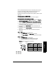
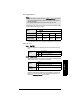
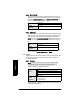
Table Of Contents
- Table of Contents
- SITRANS LR250 Overview
- Specifications
- Installation
- Wiring
- Operating via the handheld programmer
- Operating via SIMATIC PDM
- Functions in SIMATIC PDM
- Quick Start Wizard via SIMATIC PDM
- Changing parameter settings using SIMATIC PDM
- Parameters accessed via pull-down menus
- Operating via AMS Device Manager
- Functions in AMS Device Manager
- Features of AMS Device Manager
- Device Description (DD)
- Configuring a new device
- Startup
- Pull-down menu access
- Device configuration
- Quick Start Wizard via AMS Device Manager
- Maintenance and Diagnostics
- Remaining Device Lifetime [see Remaining Device Lifetime (4.2.) on page 99]
- Remaining Sensor Lifetime [see Remaining Sensor Lifetime (4.3.) on page 102]
- Service Schedule [see Service Schedule (4.4.) on page 105]
- Calibration Schedule [see Calibration Schedule (4.5.) on page 108]
- Electronic Temperature
- Wear (see Wear on page 56)
- Communication
- Security
- Device Diagnostics
- AMS Menu Structure
- Functions in AMS Device Manager
- Parameter Reference
- 1. Quick Start
- 2. Setup
- 3. Diagnostics
- 4. Service
- 5. Communication
- 6. Security
- 7. Language
- Appendix A: Alphabetical Parameter List
- Appendix B: Troubleshooting
- Appendix C: Maintenance
- Appendix D: Technical Reference
- Principles of Operation
- Echo Processing
- Analog Output
- Maximum Process Temperature Chart
- Process Pressure/Temperature derating curves
- Loop power
- Appendix E: Application Examples
- Appendix F: HART Communications
- Appendix G: ATEX Certificates
- Appendix H: Firmware Revision History
- Glossary
- Index
- LCD menu structure

Page 92 SITRANS LR250 (HART) – INSTRUCTION MANUAL 7ML19985JE03
mmmmm
Parameters
2.8.4.3. Echo Threshold
Sets the minimum echo confidence that the echo must meet in order to
prevent a Loss of Echo condition and the expiration of the Fail-safe (LOE)
timer. When Confidence (2.8.6.1.) exceeds Echo Threshold (2.8.4.3.), the
echo is accepted as a valid echo and is evaluated.
Use this feature when an incorrect material level is reported.
2.8.4.4. CLEF Range
Used mainly to allow correct level reporting for low dK materials which may
otherwise cause an incorrect reading in an empty or almost empty vessel.
CLEF range is the level below which the CLEF algorithm is used when
Hybrid is selected in Position Detect (2.8.4.2.). Above that point the Center
algorithm is used. For more detail see Position Detect (2.8.4.2.)
on page
127
).
In applications with low dK materials we recommend setting CLEF Range
to 0.5 m (1.64 ft) and Position Detect (2.8.4.2.) to Hybrid.
2.8.5. Sampling
Provides a method of checking the reliability of a new echo before accepting it
as the valid reading, based on numbers of samples above or below the
currently selected echo.
2.8.5.1. Echo Lock
Selects the measurement verification process.
For radar applications, Material Agitator is the most often-used setting, to
avoid agitator blade detection.
Values
Range: 0 to 99
Default: 5
Related
Parameters
Timer (2.5.2.)
Values
Range: 0 to 20 m (0 to 65.6 ft)
Default: 0.00 m
Related
parameters
Position Detect (2.8.4.2.)
Note: Ensure the agitator is always running while SITRANS LR250
is monitoring the vessel, to avoid stationary blade detection.
Options
Lock Off
Maximum Verification (not recommended for radar)
*
Material Agitator
Total Lock (not recommended for radar)
Related
parameters
Fill Rate (2.4.2.)
Empty rate (2.4.3.)
Sampling Up (2.8.5.2.)
Sampling Down (2.8.5.3.)