
User's Manual
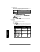
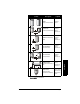
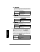
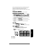
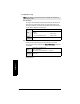
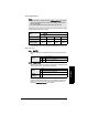
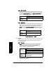
Table Of Contents
- Table of Contents
- SITRANS LR250 Overview
- Specifications
- Installation
- Wiring
- Operating via the handheld programmer
- Operating via SIMATIC PDM
- Functions in SIMATIC PDM
- Quick Start Wizard via SIMATIC PDM
- Changing parameter settings using SIMATIC PDM
- Parameters accessed via pull-down menus
- Operating via AMS Device Manager
- Functions in AMS Device Manager
- Features of AMS Device Manager
- Device Description (DD)
- Configuring a new device
- Startup
- Pull-down menu access
- Device configuration
- Quick Start Wizard via AMS Device Manager
- Maintenance and Diagnostics
- Remaining Device Lifetime [see Remaining Device Lifetime (4.2.) on page 99]
- Remaining Sensor Lifetime [see Remaining Sensor Lifetime (4.3.) on page 102]
- Service Schedule [see Service Schedule (4.4.) on page 105]
- Calibration Schedule [see Calibration Schedule (4.5.) on page 108]
- Electronic Temperature
- Wear (see Wear on page 56)
- Communication
- Security
- Device Diagnostics
- AMS Menu Structure
- Functions in AMS Device Manager
- Parameter Reference
- 1. Quick Start
- 2. Setup
- 3. Diagnostics
- 4. Service
- 5. Communication
- 6. Security
- 7. Language
- Appendix A: Alphabetical Parameter List
- Appendix B: Troubleshooting
- Appendix C: Maintenance
- Appendix D: Technical Reference
- Principles of Operation
- Echo Processing
- Analog Output
- Maximum Process Temperature Chart
- Process Pressure/Temperature derating curves
- Loop power
- Appendix E: Application Examples
- Appendix F: HART Communications
- Appendix G: ATEX Certificates
- Appendix H: Firmware Revision History
- Glossary
- Index
- LCD menu structure

7ML19985JE03 SITRANS LR250 (HART) – INSTRUCTION MANUAL Page 91
mmmmm
Parameters
2.8.3. Propagation Factor
Compensates for the change in microwave velocity due to propagation within
a metal stillpipe instead of in free space.
2.8.4. Echo select
2.8.4.1. Algorithm
Selects the algorithm to be applied to the echo profile to extract the true
echo.
2.8.4.2. Position Detect
Defines where on the echo the distance measurement is determined.
See
Position Detect (2.8.4.2.)
on page 127 for more detail.
If the vessel bottom is being reported as the level instead of the actual
material level (at low level conditions), or if the dielectric constant of the
liquid to be monitored is less than 3, we recommend setting Position to
Hybrid and CLEF Range (2.8.4.4.) to 0.5 m (1.64 ft).
Notes:
• When operating in a stillpipe, values for CLEF Range (2.8.4.4.) on page 92,
and for the propagation factor, should be set according to the pipe size.
See the table below.
• For reliable results the horn size must be close to the pipe size.
Values
Range: 0.3 to 1.5 depending on pipe size.
Default: 1.0000
Nominal Pipe Size
a)
a)
Since pipe dimensions may vary slightly, the propagation factor may also vary.
40 mm (1.5”) 50 mm (2”) 80 mm (3”) 100 mm (4”)
Propagation Factor
0.9828 0.990 0.991 0.9965
CLEF Range
(2.8.4.4.) settings
Low Cal Pt. –
700 mm
Low Cal Pt. –
700 mm
Low Cal Pt. –
1000 mm
Low Cal Pt. –
1000 mm
Options
*tFtrue First echo
LLargest echo
BLF Best of First or Largest echo
Options
Center
* Hybrid (Center and CLEF)
CLEF (Constrained Leading Edge Fit)
Related
parameters
CLEF Range (2.8.4.4.)