
User's Manual
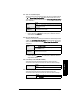
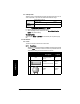
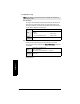
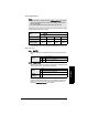
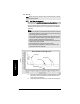
Table Of Contents
- Table of Contents
- SITRANS LR250 Overview
- Specifications
- Installation
- Wiring
- Operating via the handheld programmer
- Operating via SIMATIC PDM
- Functions in SIMATIC PDM
- Quick Start Wizard via SIMATIC PDM
- Changing parameter settings using SIMATIC PDM
- Parameters accessed via pull-down menus
- Operating via AMS Device Manager
- Functions in AMS Device Manager
- Features of AMS Device Manager
- Device Description (DD)
- Configuring a new device
- Startup
- Pull-down menu access
- Device configuration
- Quick Start Wizard via AMS Device Manager
- Maintenance and Diagnostics
- Remaining Device Lifetime [see Remaining Device Lifetime (4.2.) on page 99]
- Remaining Sensor Lifetime [see Remaining Sensor Lifetime (4.3.) on page 102]
- Service Schedule [see Service Schedule (4.4.) on page 105]
- Calibration Schedule [see Calibration Schedule (4.5.) on page 108]
- Electronic Temperature
- Wear (see Wear on page 56)
- Communication
- Security
- Device Diagnostics
- AMS Menu Structure
- Functions in AMS Device Manager
- Parameter Reference
- 1. Quick Start
- 2. Setup
- 3. Diagnostics
- 4. Service
- 5. Communication
- 6. Security
- 7. Language
- Appendix A: Alphabetical Parameter List
- Appendix B: Troubleshooting
- Appendix C: Maintenance
- Appendix D: Technical Reference
- Principles of Operation
- Echo Processing
- Analog Output
- Maximum Process Temperature Chart
- Process Pressure/Temperature derating curves
- Loop power
- Appendix E: Application Examples
- Appendix F: HART Communications
- Appendix G: ATEX Certificates
- Appendix H: Firmware Revision History
- Glossary
- Index
- LCD menu structure

Page 90 SITRANS LR250 (HART) – INSTRUCTION MANUAL 7ML19985JE03
mmmmm
Parameters
2.8. Signal Processing
2.8.1. Near Range
The range in front of the device (measured from the sensor reference point)
within which any echoes will be ignored. This is sometimes referred to as
blanking or a dead zone. The factory setting is 50 mm past the end of the horn,
and the range is dependent on the horn type.
2.8.2. Far Range
Allows the material level to drop below Low Calibration Point without
generating a Loss of Echo (LOE) state. See Sensor Mode (2.2.2.) on page 79 for
an illustration.
Use this feature if the measured surface can drop below the Low Cal. Point in
normal operation.
Note: Default settings in the parameter tables are indicated with an asterisk (*)
unless explicitly stated.
Values
Range: 0 to 20 m (0 to 65.6 ft)
Default depends on antenna.
Examples:
1.5" horn 0.185 m (7.28")
4" horn with 100 mm extension 0.270 m (10.62")
Related
parameters
Units (1.4.)
Values
Range: Min. = Low Calibration Pt.
Max. = 23 m (75.45 ft)
Default: Value for Low Calibration Pt. + 1 m (3.28 ft)
Related
parameters
Units (1.4.)