
User's Manual
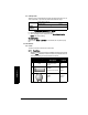
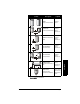
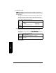
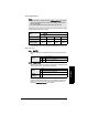
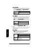
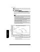
Table Of Contents
- Table of Contents
- SITRANS LR250 Overview
- Specifications
- Installation
- Wiring
- Operating via the handheld programmer
- Operating via SIMATIC PDM
- Functions in SIMATIC PDM
- Quick Start Wizard via SIMATIC PDM
- Changing parameter settings using SIMATIC PDM
- Parameters accessed via pull-down menus
- Operating via AMS Device Manager
- Functions in AMS Device Manager
- Features of AMS Device Manager
- Device Description (DD)
- Configuring a new device
- Startup
- Pull-down menu access
- Device configuration
- Quick Start Wizard via AMS Device Manager
- Maintenance and Diagnostics
- Remaining Device Lifetime [see Remaining Device Lifetime (4.2.) on page 99]
- Remaining Sensor Lifetime [see Remaining Sensor Lifetime (4.3.) on page 102]
- Service Schedule [see Service Schedule (4.4.) on page 105]
- Calibration Schedule [see Calibration Schedule (4.5.) on page 108]
- Electronic Temperature
- Wear (see Wear on page 56)
- Communication
- Security
- Device Diagnostics
- AMS Menu Structure
- Functions in AMS Device Manager
- Parameter Reference
- 1. Quick Start
- 2. Setup
- 3. Diagnostics
- 4. Service
- 5. Communication
- 6. Security
- 7. Language
- Appendix A: Alphabetical Parameter List
- Appendix B: Troubleshooting
- Appendix C: Maintenance
- Appendix D: Technical Reference
- Principles of Operation
- Echo Processing
- Analog Output
- Maximum Process Temperature Chart
- Process Pressure/Temperature derating curves
- Loop power
- Appendix E: Application Examples
- Appendix F: HART Communications
- Appendix G: ATEX Certificates
- Appendix H: Firmware Revision History
- Glossary
- Index
- LCD menu structure

7ML19985JE03 SITRANS LR250 (HART) – INSTRUCTION MANUAL Page 89
mmmmm
Parameters
Enter up to 32 level breakpoints, where the corresponding volume is known.
The values corresponding to 100% and 0% levels must be entered. The
breakpoints can be ordered from top to bottom, or the reverse.
Breakpoints are grouped into four tables: Table 1-8, Table 9-16, Table 17-24, and
Table 25-32.
Entering breakpoints via SIMATIC PDM:
• See
Using Linearization via the Quick Start wizard
on page 45.
Entering breakpoints via the handheld programmer:
a) The default unit for level values is m: to change it navigate to Setup (2.) >
Sensor (2.2.) > Units (2.2.1.), and select the desired unit.
b) Navigate to Setup (2.) > Linearization (2.7.) > Maximum Volume (2.7.1.2.),
and enter the value.
c) Go to the appropriate table for the particular breakpoint you wish to adjust:
for example, go to Table 1-8 for breakpoint 1.
d) Under Table 1-8, go to Level 1 (2.7.2.1.) to enter the level value for the
breakpoint 1.
e) Under Table 1-8, go to Volume 1 (2.7.2.2.) to enter the volume value for the
breakpoint 1
f) Repeat steps c) to e), till values have been entered for all required
breakpoints.
2.7.2.1. Level 1
a) Press RIGHT arrow to open Edit mode.
b) Enter level value and press RIGHT arrow to accept it.
c) Press Down ARROW to move to corresponding volume breakpoint.
2.7.2.2. Volume 1
a) Press RIGHT arrow to open Edit mode.
b) Enter volume value and press RIGHT arrow to accept it.
c) Press Down ARROW to move to next level breakpoint.
Example (values are for example purposes only)
2.7.3. Table 9-16
2.7.4. Table 17-24
2.7.5. Table 25-32
4
19.5
9
5
0
Breakpoint
number
3
2
1
Breakpoint
Number
Level value
(m)
Volume
value (l)
100
25500
3 9 3000
4 19.5 8000
Level
value