
User's Manual

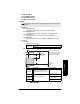
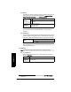
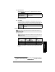
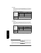
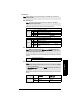
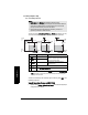
Table Of Contents
- Table of Contents
- SITRANS LR250 Overview
- Specifications
- Installation
- Wiring
- Operating via the handheld programmer
- Operating via SIMATIC PDM
- Functions in SIMATIC PDM
- Quick Start Wizard via SIMATIC PDM
- Changing parameter settings using SIMATIC PDM
- Parameters accessed via pull-down menus
- Operating via AMS Device Manager
- Functions in AMS Device Manager
- Features of AMS Device Manager
- Device Description (DD)
- Configuring a new device
- Startup
- Pull-down menu access
- Device configuration
- Quick Start Wizard via AMS Device Manager
- Maintenance and Diagnostics
- Remaining Device Lifetime [see Remaining Device Lifetime (4.2.) on page 99]
- Remaining Sensor Lifetime [see Remaining Sensor Lifetime (4.3.) on page 102]
- Service Schedule [see Service Schedule (4.4.) on page 105]
- Calibration Schedule [see Calibration Schedule (4.5.) on page 108]
- Electronic Temperature
- Wear (see Wear on page 56)
- Communication
- Security
- Device Diagnostics
- AMS Menu Structure
- Functions in AMS Device Manager
- Parameter Reference
- 1. Quick Start
- 2. Setup
- 3. Diagnostics
- 4. Service
- 5. Communication
- 6. Security
- 7. Language
- Appendix A: Alphabetical Parameter List
- Appendix B: Troubleshooting
- Appendix C: Maintenance
- Appendix D: Technical Reference
- Principles of Operation
- Echo Processing
- Analog Output
- Maximum Process Temperature Chart
- Process Pressure/Temperature derating curves
- Loop power
- Appendix E: Application Examples
- Appendix F: HART Communications
- Appendix G: ATEX Certificates
- Appendix H: Firmware Revision History
- Glossary
- Index
- LCD menu structure

7ML19985JE03 SITRANS LR250 (HART) – INSTRUCTION MANUAL Page 81
mmmmm
Parameters
2.3.2. High Calibration Pt.
Distance from sensor reference point
1)
to High Calibration Point. Units are
defined in Units (2.2.1.).
When setting the High Calibration Point value, note that echoes are ignored
within Near Range (2.2.1.11).
2.3.3. Sensor Offset
A constant offset that can be added to or subtracted from sensor value
1)
to
compensate if the sensor reference point has shifted. (For example, this could
result from adding a thicker gasket or reducing the standoff/nozzle height.)
2.4. Rate
2.4.1. Response Rate
Sets the reaction speed of the device to measurement changes.
Use a setting just faster than the maximum filling or emptying rate (whichever
is faster).
Values
Range: 0 to 20 m. Default 0.00 m
Related parameters
Units (2.2.1.)
Near Range (2.8.1.)
1)
The value produced by the echo processing which represents the distance from sen-
sor reference point to the target. (see Sensor Mode (2.2.2.) on page 79 for an illustra-
tion).
Values
Range: -99.999 to 99.999. Default: 0.00 m
Related
parameters
Units (2.2.1.)
Note: Default settings in the parameter tables are indicated with an asterisk (*)
unless explicitly stated.
Note: Changing Response Rate resets Fill Rate (2.4.2.), Empty rate (2.4.3.), and
Damping Filter (2.2.4.).
Response Rate
(2.4.1.)
Fill Rate
(2.4.2.)
Empty rate
(2.4.3.)
Damping Filter
(2.2.4.)
* Slow 0.1 m/min (0.32 ft/min) 10 s
Medium 1.0 m/min (3.28 ft/min) 10 s
Fast 10.0 m/min (32.8 ft/min) 0 s