
User's Manual

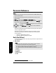
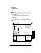
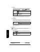
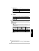
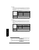
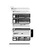
Table Of Contents
- Table of Contents
- SITRANS LR250 Overview
- Specifications
- Installation
- Wiring
- Operating via the handheld programmer
- Operating via SIMATIC PDM
- Functions in SIMATIC PDM
- Quick Start Wizard via SIMATIC PDM
- Changing parameter settings using SIMATIC PDM
- Parameters accessed via pull-down menus
- Operating via AMS Device Manager
- Functions in AMS Device Manager
- Features of AMS Device Manager
- Device Description (DD)
- Configuring a new device
- Startup
- Pull-down menu access
- Device configuration
- Quick Start Wizard via AMS Device Manager
- Maintenance and Diagnostics
- Remaining Device Lifetime [see Remaining Device Lifetime (4.2.) on page 99]
- Remaining Sensor Lifetime [see Remaining Sensor Lifetime (4.3.) on page 102]
- Service Schedule [see Service Schedule (4.4.) on page 105]
- Calibration Schedule [see Calibration Schedule (4.5.) on page 108]
- Electronic Temperature
- Wear (see Wear on page 56)
- Communication
- Security
- Device Diagnostics
- AMS Menu Structure
- Functions in AMS Device Manager
- Parameter Reference
- 1. Quick Start
- 2. Setup
- 3. Diagnostics
- 4. Service
- 5. Communication
- 6. Security
- 7. Language
- Appendix A: Alphabetical Parameter List
- Appendix B: Troubleshooting
- Appendix C: Maintenance
- Appendix D: Technical Reference
- Principles of Operation
- Echo Processing
- Analog Output
- Maximum Process Temperature Chart
- Process Pressure/Temperature derating curves
- Loop power
- Appendix E: Application Examples
- Appendix F: HART Communications
- Appendix G: ATEX Certificates
- Appendix H: Firmware Revision History
- Glossary
- Index
- LCD menu structure

Page 80 SITRANS LR250 (HART) – INSTRUCTION MANUAL 7ML19985JE03
mmmmm
Parameters
2.2.3. Material
Automatically configures the device to operate in the chosen application type,
by changing one or more of the following parameters: Propagation Factor
(2.8.3.), Position Detect (2.8.4.2.), and/or CLEF Range (2.8.4.4.).
You can configure each of the related parameters, to suit your particular
application.
2.2.4. Damping Filter
The time constant for the damping filter. The damping filter smooths out the re-
sponse to a sudden change in level. This is an exponential filter and the engi-
neering unit is always in seconds (see Damping on page 132 for more detail).
Antenna
Read only. Identifies horn configuration (Near Range (blanking) distance is au-
tomatically adjusted to suit).
2.3. Calibration
2.3.1. Low Calibration Pt.
Distance from sensor reference point
1)
to Low Calibration Point.
Units are
defined in Units (2.2.1.)
Options
*
LIQUID
LIQUID LOW DK
a)
(low dielectric liquid – CLEF algorithm
enabled)
a)
dK < 3.0
Related
parameters
Propagation Factor (2.8.3.)
Position Detect (2.8.4.2.)
CLEF Range (2.8.4.4.)
Values
Range: 0 to 100.000 s
Default: 10.000 s
Note: We recommend using the Quick Start wizard to configure the device.
1)
The point from which level measurement is referenced (see Sensor Mode (2.2.2.) for
an illustration).
Values
Range: 0 to 20 m. Default 20.00 m
Related
parameters
Units (2.2.1.)
Far Range (2.8.2.)