
User's Manual
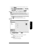
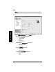
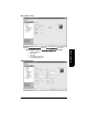
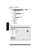
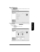
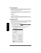
Table Of Contents
- Table of Contents
- SITRANS LR250 Overview
- Specifications
- Installation
- Wiring
- Operating via the handheld programmer
- Operating via SIMATIC PDM
- Functions in SIMATIC PDM
- Quick Start Wizard via SIMATIC PDM
- Changing parameter settings using SIMATIC PDM
- Parameters accessed via pull-down menus
- Operating via AMS Device Manager
- Functions in AMS Device Manager
- Features of AMS Device Manager
- Device Description (DD)
- Configuring a new device
- Startup
- Pull-down menu access
- Device configuration
- Quick Start Wizard via AMS Device Manager
- Maintenance and Diagnostics
- Remaining Device Lifetime [see Remaining Device Lifetime (4.2.) on page 99]
- Remaining Sensor Lifetime [see Remaining Sensor Lifetime (4.3.) on page 102]
- Service Schedule [see Service Schedule (4.4.) on page 105]
- Calibration Schedule [see Calibration Schedule (4.5.) on page 108]
- Electronic Temperature
- Wear (see Wear on page 56)
- Communication
- Security
- Device Diagnostics
- AMS Menu Structure
- Functions in AMS Device Manager
- Parameter Reference
- 1. Quick Start
- 2. Setup
- 3. Diagnostics
- 4. Service
- 5. Communication
- 6. Security
- 7. Language
- Appendix A: Alphabetical Parameter List
- Appendix B: Troubleshooting
- Appendix C: Maintenance
- Appendix D: Technical Reference
- Principles of Operation
- Echo Processing
- Analog Output
- Maximum Process Temperature Chart
- Process Pressure/Temperature derating curves
- Loop power
- Appendix E: Application Examples
- Appendix F: HART Communications
- Appendix G: ATEX Certificates
- Appendix H: Firmware Revision History
- Glossary
- Index
- LCD menu structure

Page 74 SITRANS LR250 (HART) – INSTRUCTION MANUAL 7ML19985JE03
mmmmm
AMS Device Manger
Configure/Setup (continued)
Setup/Sensor (continued)
Calibration
Low Calibration Point
High Calibration Point’
Sensor Offset
Rate
Response Rate
Fill rate/minute
Empty rate/minute
Fail-safe
Timer
Material Level
Level
Analog Output Scaling
Analog Output Scaling
mA Output Function
Start of Scale
Full Scale
Control Range lower limit
Control Range upper limit
Linearization
Linearization
Vessel Shape
Vessel dimensions
Max. volume
Dimension A
Dimension L
Characteristic
Signal Processing
General
Range
Near Range
Far Range
Propagation Factor
Echo Select
Algorithm
Position Detect
Echo Threshold
CLEF Range
Sampling
Echo Lock
Sampling Up
Sampling Down
Echo Lock Window.