
User's Manual
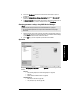
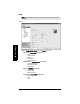
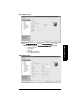
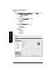
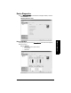
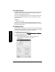
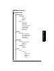
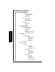
Table Of Contents
- Table of Contents
- SITRANS LR250 Overview
- Specifications
- Installation
- Wiring
- Operating via the handheld programmer
- Operating via SIMATIC PDM
- Functions in SIMATIC PDM
- Quick Start Wizard via SIMATIC PDM
- Changing parameter settings using SIMATIC PDM
- Parameters accessed via pull-down menus
- Operating via AMS Device Manager
- Functions in AMS Device Manager
- Features of AMS Device Manager
- Device Description (DD)
- Configuring a new device
- Startup
- Pull-down menu access
- Device configuration
- Quick Start Wizard via AMS Device Manager
- Maintenance and Diagnostics
- Remaining Device Lifetime [see Remaining Device Lifetime (4.2.) on page 99]
- Remaining Sensor Lifetime [see Remaining Sensor Lifetime (4.3.) on page 102]
- Service Schedule [see Service Schedule (4.4.) on page 105]
- Calibration Schedule [see Calibration Schedule (4.5.) on page 108]
- Electronic Temperature
- Wear (see Wear on page 56)
- Communication
- Security
- Device Diagnostics
- AMS Menu Structure
- Functions in AMS Device Manager
- Parameter Reference
- 1. Quick Start
- 2. Setup
- 3. Diagnostics
- 4. Service
- 5. Communication
- 6. Security
- 7. Language
- Appendix A: Alphabetical Parameter List
- Appendix B: Troubleshooting
- Appendix C: Maintenance
- Appendix D: Technical Reference
- Principles of Operation
- Echo Processing
- Analog Output
- Maximum Process Temperature Chart
- Process Pressure/Temperature derating curves
- Loop power
- Appendix E: Application Examples
- Appendix F: HART Communications
- Appendix G: ATEX Certificates
- Appendix H: Firmware Revision History
- Glossary
- Index
- LCD menu structure

7ML19985JE03 SITRANS LR250 (HART) – INSTRUCTION MANUAL Page 65
mmmmm
AMS Device Manger
6) Click on the Breakpoints tab and enter values for level and volume for up to 32
breakpoints.
7) Navigate to Configure/Setup > Setup > Linearization and click on Characteristic to
preview the characteristic curve of the vessel breakpoints.
8) In Step 5 – Summary check parameter values. Click on the appropriate step menu to
return and revise values, or click on a different menu to exit Quick Start.
Changing parameter settings using AMS Device Manager
1) Adjust parameter values in the parameter value field in Configure/Setup view, then
click on Apply to write the new values to the device. The parameter field will display
in yellow until the value has been written to the device.
2) Click on OK only if you wish to update all parameters and exit AMS.
Operation
Navigate to Configure/Setup > Operation and click on Operation to open the dialog window for
access to:
General:
• Select Analog Output (see
Select Analog Output
on page 55)
•D/A Trim
•Master Reset (see
Master Reset
on page 56)
Simulation/Test
• Self Test (see
Self Test
on page 55)
• Loop Test (see
Loop Test
on page 56)
Notes:
• For a complete list of parameters, see
Parameter Reference
on page 78.
• For more detailed explanations of the parameters listed below see the pages
referenced.