
User's Manual
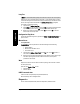
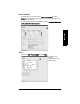
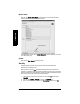

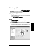
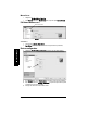
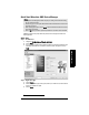
Table Of Contents
- Table of Contents
- SITRANS LR250 Overview
- Specifications
- Installation
- Wiring
- Operating via the handheld programmer
- Operating via SIMATIC PDM
- Functions in SIMATIC PDM
- Quick Start Wizard via SIMATIC PDM
- Changing parameter settings using SIMATIC PDM
- Parameters accessed via pull-down menus
- Operating via AMS Device Manager
- Functions in AMS Device Manager
- Features of AMS Device Manager
- Device Description (DD)
- Configuring a new device
- Startup
- Pull-down menu access
- Device configuration
- Quick Start Wizard via AMS Device Manager
- Maintenance and Diagnostics
- Remaining Device Lifetime [see Remaining Device Lifetime (4.2.) on page 99]
- Remaining Sensor Lifetime [see Remaining Sensor Lifetime (4.3.) on page 102]
- Service Schedule [see Service Schedule (4.4.) on page 105]
- Calibration Schedule [see Calibration Schedule (4.5.) on page 108]
- Electronic Temperature
- Wear (see Wear on page 56)
- Communication
- Security
- Device Diagnostics
- AMS Menu Structure
- Functions in AMS Device Manager
- Parameter Reference
- 1. Quick Start
- 2. Setup
- 3. Diagnostics
- 4. Service
- 5. Communication
- 6. Security
- 7. Language
- Appendix A: Alphabetical Parameter List
- Appendix B: Troubleshooting
- Appendix C: Maintenance
- Appendix D: Technical Reference
- Principles of Operation
- Echo Processing
- Analog Output
- Maximum Process Temperature Chart
- Process Pressure/Temperature derating curves
- Loop power
- Appendix E: Application Examples
- Appendix F: HART Communications
- Appendix G: ATEX Certificates
- Appendix H: Firmware Revision History
- Glossary
- Index
- LCD menu structure

Page 56 SITRANS LR250 (HART) – INSTRUCTION MANUAL 7ML19985JE03
mmmmm
SIMATIC PDM
Loop Test
Allows you to input a simulated value (4 mA, 20 mA, or a user-defined value) in order to
test the functioning of the mA connections during commissioning or maintenance of the
device. (The range is 3.56 mA to 22.6 mA: see
mA Output Value (2.6.6.)
on page 86.)
To simulate a user-defined mA value:
1) Open the menu Device – Loop Test.
2) Select Other, enter the new value, and click on OK. The message ’Field Device fixed
at [new value]’ appears. Click on OK. The Loop Test window remains open.
3) When you are ready to end simulation, select End and click on OK to return the
device to the actual output value.
Configuration Flag Reset
To reset the configuration flag to zero, open the menu Device – Configuration Flag Reset and
perform a reset.
Master Reset
Factory Defaults
Factory Defaults resets all parameters to the default settings with the following
exceptions:
• Device Address
• Write Protect and PIN to unlock
• Learned TVT curve
1) Open the menu Device – Master Reset, select Yes, and click on OK to perform a
reset to Factory Defaults.
2) After the reset is complete upload parameters to the PC/PG. (If you are performing a
reset after replacing the device with a different instrument, do not upload
parameters to the PC/PG).
Wear
Reports the number of hours the device has been operating, and the number of times it
has been powered up.
Open the menu Device – Wear to view:
• Powered Days
• Power-on Resets
HART Communication
Sets the number of request/response preambles (default 5).
We recommend you do not change this value.
Diagnostics
You can monitor level/volume trends, electronics temperature, and device status.
Note: The simulated AO (Analog Output) value influences output to the control system.