
User's Manual
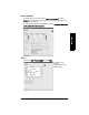
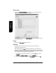

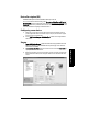
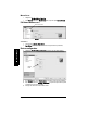
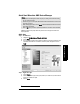
Table Of Contents
- Table of Contents
- SITRANS LR250 Overview
- Specifications
- Installation
- Wiring
- Operating via the handheld programmer
- Operating via SIMATIC PDM
- Functions in SIMATIC PDM
- Quick Start Wizard via SIMATIC PDM
- Changing parameter settings using SIMATIC PDM
- Parameters accessed via pull-down menus
- Operating via AMS Device Manager
- Functions in AMS Device Manager
- Features of AMS Device Manager
- Device Description (DD)
- Configuring a new device
- Startup
- Pull-down menu access
- Device configuration
- Quick Start Wizard via AMS Device Manager
- Maintenance and Diagnostics
- Remaining Device Lifetime [see Remaining Device Lifetime (4.2.) on page 99]
- Remaining Sensor Lifetime [see Remaining Sensor Lifetime (4.3.) on page 102]
- Service Schedule [see Service Schedule (4.4.) on page 105]
- Calibration Schedule [see Calibration Schedule (4.5.) on page 108]
- Electronic Temperature
- Wear (see Wear on page 56)
- Communication
- Security
- Device Diagnostics
- AMS Menu Structure
- Functions in AMS Device Manager
- Parameter Reference
- 1. Quick Start
- 2. Setup
- 3. Diagnostics
- 4. Service
- 5. Communication
- 6. Security
- 7. Language
- Appendix A: Alphabetical Parameter List
- Appendix B: Troubleshooting
- Appendix C: Maintenance
- Appendix D: Technical Reference
- Principles of Operation
- Echo Processing
- Analog Output
- Maximum Process Temperature Chart
- Process Pressure/Temperature derating curves
- Loop power
- Appendix E: Application Examples
- Appendix F: HART Communications
- Appendix G: ATEX Certificates
- Appendix H: Firmware Revision History
- Glossary
- Index
- LCD menu structure

7ML19985JE03 SITRANS LR250 (HART) – INSTRUCTION MANUAL Page 55
mmmmm
SIMATIC PDM
2) Modify desired values, and click on Write.
3) Click on Read, to see the effects of your modification.
4) If desired, set reminders for either or both of Reminder 1 (Required)/Reminder 2
(Demanded).
5) Click on Snooze to add a year to the Total Expected Device Life.
To set Service/Calibration schedules:
1) Open the menu Device – Maintenance, and click on the Service/Calibration
Schedule tab.
2) Modify desired values, and click on Write.
3) Click on Read, to see the effects of your modification.
4) If desired, set reminders for either or both of Reminder 1 (Required)/Reminder 2
(Demanded).
5) Click on Service/Calibration Performed to reset the schedule.
Select Analog Output
Allows you to set the mA Output to report Level, Distance. See Current Output Function
on page 84 for an illustration.
If a volume application is selected, mA Output is automatically set to Volume. (See Analog
Output on page 132 for more details.)
1) Open the menu Device – Select Analog Output.
2) The Select Analog Output window displays the current setting: click on OK.
3) Select a different setting and click on OK.
4) The Select Analog Output window displays the new setting: click on OK.
Self Test
Checks memory (RAM and Flash). If there are no errors, returns the message ’Self Test
OK.’ If errors are found, returns the message ’Self Test Fails’.
Open the menu Device – Self Test, select the option Yes and click on OK.