
User's Manual
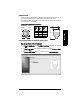
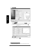
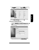
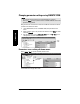
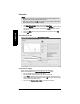
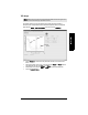
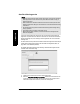
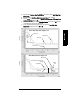
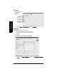
Table Of Contents
- Table of Contents
- SITRANS LR250 Overview
- Specifications
- Installation
- Wiring
- Operating via the handheld programmer
- Operating via SIMATIC PDM
- Functions in SIMATIC PDM
- Quick Start Wizard via SIMATIC PDM
- Changing parameter settings using SIMATIC PDM
- Parameters accessed via pull-down menus
- Operating via AMS Device Manager
- Functions in AMS Device Manager
- Features of AMS Device Manager
- Device Description (DD)
- Configuring a new device
- Startup
- Pull-down menu access
- Device configuration
- Quick Start Wizard via AMS Device Manager
- Maintenance and Diagnostics
- Remaining Device Lifetime [see Remaining Device Lifetime (4.2.) on page 99]
- Remaining Sensor Lifetime [see Remaining Sensor Lifetime (4.3.) on page 102]
- Service Schedule [see Service Schedule (4.4.) on page 105]
- Calibration Schedule [see Calibration Schedule (4.5.) on page 108]
- Electronic Temperature
- Wear (see Wear on page 56)
- Communication
- Security
- Device Diagnostics
- AMS Menu Structure
- Functions in AMS Device Manager
- Parameter Reference
- 1. Quick Start
- 2. Setup
- 3. Diagnostics
- 4. Service
- 5. Communication
- 6. Security
- 7. Language
- Appendix A: Alphabetical Parameter List
- Appendix B: Troubleshooting
- Appendix C: Maintenance
- Appendix D: Technical Reference
- Principles of Operation
- Echo Processing
- Analog Output
- Maximum Process Temperature Chart
- Process Pressure/Temperature derating curves
- Loop power
- Appendix E: Application Examples
- Appendix F: HART Communications
- Appendix G: ATEX Certificates
- Appendix H: Firmware Revision History
- Glossary
- Index
- LCD menu structure

Page 52 SITRANS LR250 (HART) – INSTRUCTION MANUAL 7ML19985JE03
mmmmm
SIMATIC PDM
Auto False Echo Suppression
If you have a vessel with known obstructions, we recommend using Auto False Echo
Suppression to prevent false echo detection. This feature can also be used if the device
displays a false high level, or the reading is fluctuating between the correct level and a
false high level.
The device learns the echo profile over the whole measurement range and the TVT is shaped
around all echoes present at that moment. (See
Auto False Echo Suppression (2.8.7.1.)
on
page 130 for a more detailed explanation.)
The learned TVT will be applied over a specified range. The default TVT is applied over the
remainder of the measurement range.
1) Make sure the material level is below all known obstructions.
2) Determine Auto False Echo Suppression Range. Measure the actual distance from
the sensor reference point to the material surface using a rope or tape measure.
Subtract 0.5 m (20") from this distance, and use the resulting value.
Notes:
• Make sure material level is below all known obstructions at the moment Auto False
Echo Suppression is used to learn the echo profile. We recommend an empty or
almost empty vessel.
• Note the distance to material level when the environment is learned, and set Auto
False Echo Suppression Range to a shorter distance to avoid the material echo being
screened out.
• Set Auto False Echo Suppression and Auto False Echo Suppression Range during
startup, if possible.
• If the vessel contains an agitator it should be running.
• Before adjusting these parameters, rotate the instrument for best signal (lower
false-echo amplitude).