
User's Manual
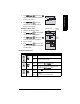
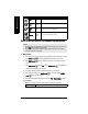
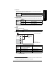
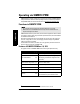
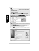
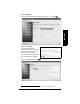
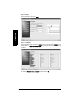
Table Of Contents
- Table of Contents
- SITRANS LR250 Overview
- Specifications
- Installation
- Wiring
- Operating via the handheld programmer
- Operating via SIMATIC PDM
- Functions in SIMATIC PDM
- Quick Start Wizard via SIMATIC PDM
- Changing parameter settings using SIMATIC PDM
- Parameters accessed via pull-down menus
- Operating via AMS Device Manager
- Functions in AMS Device Manager
- Features of AMS Device Manager
- Device Description (DD)
- Configuring a new device
- Startup
- Pull-down menu access
- Device configuration
- Quick Start Wizard via AMS Device Manager
- Maintenance and Diagnostics
- Remaining Device Lifetime [see Remaining Device Lifetime (4.2.) on page 99]
- Remaining Sensor Lifetime [see Remaining Sensor Lifetime (4.3.) on page 102]
- Service Schedule [see Service Schedule (4.4.) on page 105]
- Calibration Schedule [see Calibration Schedule (4.5.) on page 108]
- Electronic Temperature
- Wear (see Wear on page 56)
- Communication
- Security
- Device Diagnostics
- AMS Menu Structure
- Functions in AMS Device Manager
- Parameter Reference
- 1. Quick Start
- 2. Setup
- 3. Diagnostics
- 4. Service
- 5. Communication
- 6. Security
- 7. Language
- Appendix A: Alphabetical Parameter List
- Appendix B: Troubleshooting
- Appendix C: Maintenance
- Appendix D: Technical Reference
- Principles of Operation
- Echo Processing
- Analog Output
- Maximum Process Temperature Chart
- Process Pressure/Temperature derating curves
- Loop power
- Appendix E: Application Examples
- Appendix F: HART Communications
- Appendix G: ATEX Certificates
- Appendix H: Firmware Revision History
- Glossary
- Index
- LCD menu structure

7ML19985JE03 SITRANS LR250 (HART) – INSTRUCTION MANUAL Page 37
mmmmm
Quick Start: local
1.2. Material
Selects the appropriate echo processing algorithms for the material (see Position
Detect (2.8.4.2.) on page 127 for more detail).
1.3. Response Rate
Sets the reaction speed of the device to measurement changes in the target range.
Use a setting just faster than the maximum filling or emptying rate (whichever is
greater).
1.4. Units
Sensor measurement units.
1.5. Operation Mode
1)
Options
LIQUID
LIQUID LOW DK
a)
(low dielectric liquid – CLEF
algorithm enabled
)
a)
dK < 3.0
Options
Response
Rate (1.3.)
Fill Rate (2.4.2.)/Empty rate (2.4.3.)
SLOW 0.1 m/min (0.32 ft/min)
MED 1.0 m/min (3.28 ft/min)
FAST 10.0 m/min (32.8 ft/min)
Options
M, CM, MM, FT, IN
Operation Description Reference point
NO
SERVICE
Measurement and associated loop cur-
rent are not updated, and the device
defaults to Fail-safe mode
a)
.
a)
See Material Level (2.5.1.) on page 83 for more detail.
LEVEL Distance to material surface Low Calibration Point
SPACE Distance to material surface High Calibration Point
DISTANCE Distance to material surface Sensor Reference Point
1)
The point from which High and Low Calibration points are referenced: see
Dimensions
on page 12 and
Flanged Horn with extension
on page 14.
High Cal. Point
(process full
level)
Low Cal. Point
(process empty level)
Level
Space
Distance
sensor reference point
1)