
User's Manual
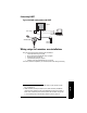
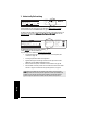
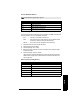
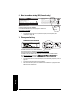
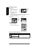
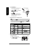
Table Of Contents
- Table of Contents
- SITRANS LR250 Overview
- Specifications
- Installation
- Wiring
- Operating via the handheld programmer
- Operating via SIMATIC PDM
- Functions in SIMATIC PDM
- Quick Start Wizard via SIMATIC PDM
- Changing parameter settings using SIMATIC PDM
- Parameters accessed via pull-down menus
- Operating via AMS Device Manager
- Functions in AMS Device Manager
- Features of AMS Device Manager
- Device Description (DD)
- Configuring a new device
- Startup
- Pull-down menu access
- Device configuration
- Quick Start Wizard via AMS Device Manager
- Maintenance and Diagnostics
- Remaining Device Lifetime [see Remaining Device Lifetime (4.2.) on page 99]
- Remaining Sensor Lifetime [see Remaining Sensor Lifetime (4.3.) on page 102]
- Service Schedule [see Service Schedule (4.4.) on page 105]
- Calibration Schedule [see Calibration Schedule (4.5.) on page 108]
- Electronic Temperature
- Wear (see Wear on page 56)
- Communication
- Security
- Device Diagnostics
- AMS Menu Structure
- Functions in AMS Device Manager
- Parameter Reference
- 1. Quick Start
- 2. Setup
- 3. Diagnostics
- 4. Service
- 5. Communication
- 6. Security
- 7. Language
- Appendix A: Alphabetical Parameter List
- Appendix B: Troubleshooting
- Appendix C: Maintenance
- Appendix D: Technical Reference
- Principles of Operation
- Echo Processing
- Analog Output
- Maximum Process Temperature Chart
- Process Pressure/Temperature derating curves
- Loop power
- Appendix E: Application Examples
- Appendix F: HART Communications
- Appendix G: ATEX Certificates
- Appendix H: Firmware Revision History
- Glossary
- Index
- LCD menu structure

7ML19985JE03 SITRANS LR250 (HART) – INSTRUCTION MANUAL Page 27
mmmmm
Wiring
Passive Shunt Diode Barriers
How to select a passive barrier for SITRANS LR250
To make sure that the barrier safety description is suitable for the LR250 Intrinsically Safe
(IS) input parameters, carry out the following calculations:
Re-e = max. end-to-end resistance of the barrier
Rloop = loop resistance (total of cable resistance plus any additional series
resistance, for example, PLC inputs and/or displays)
Vbarrier = value of any non-linear voltage drops due to the barrier
1) Determine the value for Re-e from the data sheet.
2) Calculate the total value for Rloop.
3) Calculate Rworking = Re-e + Rloop.
4) Determine the value of Vbarrier from the barrier data sheet (for example, voltage
drops due to diodes).
5) Calculate Vworking = Vsupply – Vbarrier.
Use the values for Vworking and Rworking to confirm that operation is within the
shaded area of the graph
Curve 1 (General Purpose, Intrinsically Safe, Non-incen-
dive)
on page 140.
Active barriers (repeating barriers)
Note: A well regulated supply voltage is required.
Manufacturer Part Number
MTL 787SP+ (Dual Channel)
MTL 7787P+ (Dual Channel)
Stahl 9001/01-280-100-10 (Single Channel)
Stahl 9002/01-280-110-10 (Dual Channel)
Manufacturer Part Number
MTL 706
MTL 7206
Siemens SITRANS I 7NG4122
Stahl 9001/51-280-110-14
MTL E02009
MTL E02010