
User's Manual
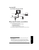
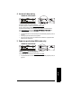
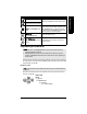
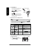
Table Of Contents
- Table of Contents
- SITRANS LR250 Overview
- Specifications
- Installation
- Wiring
- Operating via the handheld programmer
- Operating via SIMATIC PDM
- Functions in SIMATIC PDM
- Quick Start Wizard via SIMATIC PDM
- Changing parameter settings using SIMATIC PDM
- Parameters accessed via pull-down menus
- Operating via AMS Device Manager
- Functions in AMS Device Manager
- Features of AMS Device Manager
- Device Description (DD)
- Configuring a new device
- Startup
- Pull-down menu access
- Device configuration
- Quick Start Wizard via AMS Device Manager
- Maintenance and Diagnostics
- Remaining Device Lifetime [see Remaining Device Lifetime (4.2.) on page 99]
- Remaining Sensor Lifetime [see Remaining Sensor Lifetime (4.3.) on page 102]
- Service Schedule [see Service Schedule (4.4.) on page 105]
- Calibration Schedule [see Calibration Schedule (4.5.) on page 108]
- Electronic Temperature
- Wear (see Wear on page 56)
- Communication
- Security
- Device Diagnostics
- AMS Menu Structure
- Functions in AMS Device Manager
- Parameter Reference
- 1. Quick Start
- 2. Setup
- 3. Diagnostics
- 4. Service
- 5. Communication
- 6. Security
- 7. Language
- Appendix A: Alphabetical Parameter List
- Appendix B: Troubleshooting
- Appendix C: Maintenance
- Appendix D: Technical Reference
- Principles of Operation
- Echo Processing
- Analog Output
- Maximum Process Temperature Chart
- Process Pressure/Temperature derating curves
- Loop power
- Appendix E: Application Examples
- Appendix F: HART Communications
- Appendix G: ATEX Certificates
- Appendix H: Firmware Revision History
- Glossary
- Index
- LCD menu structure

7ML19985JE03 SITRANS LR250 (HART) – INSTRUCTION MANUAL Page 25
mmmmm
Wiring
Connecting HART
1)2)
Wiring setups for hazardous area installations
There are five wiring options for hazardous area installations:
•
Intrinsically Safe wiring
on page 26
•
Non-incendive wiring (US/Canada only)
on page 28
•
Flameproof wiring
on page 28
•
Increased safety wiring
on page 29
•
Explosion-proof wiring (US/Canada only)
on page 29
In all cases, check the nameplate on your instrument, and confirm the approval rating.
1)
Depending on the system design, the power supply may be separate from the
PLC, or integral to it.
2)
HART resistance (total loop resistance, that is, cable resistance plus 250 Ohm
[resistor]) must be limited according to the allowable operating area as shown in
either
Curve 1 (General Purpose, Intrinsically Safe, Non-incendive)
on page 140
or
Curve 2 (Flameproof, Increased Safety, Explosion-proof)
on page 141.
active PLC
HART modem
SITRANS LR250
power supply
(1)
Typical PLC/mA configuration with HART
R= 250 Ω
(2)
HART
communicator