
User's Manual
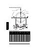

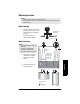
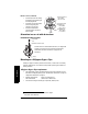
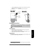
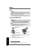
Table Of Contents
- Table of Contents
- SITRANS LR250 Overview
- Specifications
- Installation
- Wiring
- Operating via the handheld programmer
- Operating via SIMATIC PDM
- Functions in SIMATIC PDM
- Quick Start Wizard via SIMATIC PDM
- Changing parameter settings using SIMATIC PDM
- Parameters accessed via pull-down menus
- Operating via AMS Device Manager
- Functions in AMS Device Manager
- Features of AMS Device Manager
- Device Description (DD)
- Configuring a new device
- Startup
- Pull-down menu access
- Device configuration
- Quick Start Wizard via AMS Device Manager
- Maintenance and Diagnostics
- Remaining Device Lifetime [see Remaining Device Lifetime (4.2.) on page 99]
- Remaining Sensor Lifetime [see Remaining Sensor Lifetime (4.3.) on page 102]
- Service Schedule [see Service Schedule (4.4.) on page 105]
- Calibration Schedule [see Calibration Schedule (4.5.) on page 108]
- Electronic Temperature
- Wear (see Wear on page 56)
- Communication
- Security
- Device Diagnostics
- AMS Menu Structure
- Functions in AMS Device Manager
- Parameter Reference
- 1. Quick Start
- 2. Setup
- 3. Diagnostics
- 4. Service
- 5. Communication
- 6. Security
- 7. Language
- Appendix A: Alphabetical Parameter List
- Appendix B: Troubleshooting
- Appendix C: Maintenance
- Appendix D: Technical Reference
- Principles of Operation
- Echo Processing
- Analog Output
- Maximum Process Temperature Chart
- Process Pressure/Temperature derating curves
- Loop power
- Appendix E: Application Examples
- Appendix F: HART Communications
- Appendix G: ATEX Certificates
- Appendix H: Firmware Revision History
- Glossary
- Index
- LCD menu structure

Page 24 SITRANS LR250 (HART) – INSTRUCTION MANUAL 7ML19985JE03
mmmmm
Wiring
Wiring
Power
Connecting
SITRANS LR250
1)
2)
1) Strip the cable jacket for approximately 70 mm (2.75") from the end of the cable, and
thread the wires through the gland
2)
.
2) Connect the wires to the terminals as shown: the polarity is identified on the
terminal block.
3) Ground the instrument according to local regulations.
4) Tighten the gland to form a good seal.
WARNINGS:
The DC input terminals shall be supplied from a source providing
electrical isolation between the input and output, in order to meet
the applicable safety requirements of IEC 61010-1.
All field wiring must have insulation suitable for rated voltages.
WARNINGS:
• Check the nameplate on your instrument, to verify the approval rating.
• Use appropriate conduit seals to maintain IP or NEMA rating.
•See
Wiring setups for hazardous area installations
on page 25.
Notes:
• Use twisted pair cable: AWG 22 to 14 (0.34 mm
2
to 2.5 mm
2
).
• Separate cables and conduits may be required to conform to standard
instrumentation wiring practices or electrical codes.
1)
May be shipped with the device.
2)
If cable is routed through conduit, use only approved suitable-size hubs for
waterproof applications.
Use a 2 mm Allen key to
loosen the lid-lock set
screw.
optional cable gland
1)
2)
(or NPT cable entry
2)
)
plug (IP 68)
cable shield
(if used)