
User's Manual

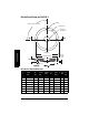
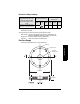
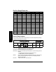

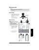
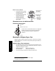
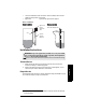
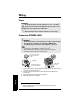
Table Of Contents
- Table of Contents
- SITRANS LR250 Overview
- Specifications
- Installation
- Wiring
- Operating via the handheld programmer
- Operating via SIMATIC PDM
- Functions in SIMATIC PDM
- Quick Start Wizard via SIMATIC PDM
- Changing parameter settings using SIMATIC PDM
- Parameters accessed via pull-down menus
- Operating via AMS Device Manager
- Functions in AMS Device Manager
- Features of AMS Device Manager
- Device Description (DD)
- Configuring a new device
- Startup
- Pull-down menu access
- Device configuration
- Quick Start Wizard via AMS Device Manager
- Maintenance and Diagnostics
- Remaining Device Lifetime [see Remaining Device Lifetime (4.2.) on page 99]
- Remaining Sensor Lifetime [see Remaining Sensor Lifetime (4.3.) on page 102]
- Service Schedule [see Service Schedule (4.4.) on page 105]
- Calibration Schedule [see Calibration Schedule (4.5.) on page 108]
- Electronic Temperature
- Wear (see Wear on page 56)
- Communication
- Security
- Device Diagnostics
- AMS Menu Structure
- Functions in AMS Device Manager
- Parameter Reference
- 1. Quick Start
- 2. Setup
- 3. Diagnostics
- 4. Service
- 5. Communication
- 6. Security
- 7. Language
- Appendix A: Alphabetical Parameter List
- Appendix B: Troubleshooting
- Appendix C: Maintenance
- Appendix D: Technical Reference
- Principles of Operation
- Echo Processing
- Analog Output
- Maximum Process Temperature Chart
- Process Pressure/Temperature derating curves
- Loop power
- Appendix E: Application Examples
- Appendix F: HART Communications
- Appendix G: ATEX Certificates
- Appendix H: Firmware Revision History
- Glossary
- Index
- LCD menu structure

Page 22 SITRANS LR250 (HART) – INSTRUCTION MANUAL 7ML19985JE03
mmmmm
Installation
Nozzle location (continued)
• Provide easy access for viewing
the display and programming via
the hand programmer.
• Provide an environment suitable
to the housing rating and
materials of construction.
• Provide a sunshield if the
instrument will be mounted in
direct sunlight.
Orientation in a vessel with obstructions
Polarization reference point
Mounting on a Stillpipe or Bypass Pipe
A stillpipe or bypass is used for products with a low dK
1)
, or when vortex or extremely
turbulent conditions exist. It can also be used to provide optimum signal conditions on
foaming materials.
Stillpipe or Bypass Pipe requirements
• The pipe diameter must be matched with the horn size. Use the largest horn size
that will fit the stillpipe/bypass pipe (see
Threaded Horn dimensions
on page 13 or
Flanged Horn dimensions
on page 15).
• Suitable pipe diameters: 40 mm (1.5") to 100 mm (4”).
Not recommended: (152.4 mm/ 6" or 203.2 mm/ 8")
• One continuous length of metallic pipe is preferred, without joints
2)
.
1)
See
Dielectric constant of material measured
on page 8.
2)
Bad joints create reflections.
ambient temperature
–40 °C to 80 °C
(–40 °F to 176 °F)
process temperature
with FKM O-ring:
–40 to +200 °C
(–40 to +392 °F)
with FFKM O-ring:
–20 to +200 °C
(–4 to +392 °F)
polarization reference point
polarization
axis
display
For best results on a vessel with obstructions, or a stillpipe with
openings, orient the front or back of the device toward the
obstructions (see
Device orientation
on page 23 for an
illustration).