
User's Manual
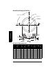
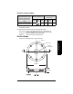
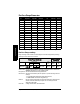

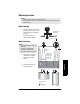
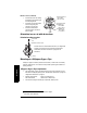
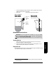
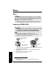
Table Of Contents
- Table of Contents
- SITRANS LR250 Overview
- Specifications
- Installation
- Wiring
- Operating via the handheld programmer
- Operating via SIMATIC PDM
- Functions in SIMATIC PDM
- Quick Start Wizard via SIMATIC PDM
- Changing parameter settings using SIMATIC PDM
- Parameters accessed via pull-down menus
- Operating via AMS Device Manager
- Functions in AMS Device Manager
- Features of AMS Device Manager
- Device Description (DD)
- Configuring a new device
- Startup
- Pull-down menu access
- Device configuration
- Quick Start Wizard via AMS Device Manager
- Maintenance and Diagnostics
- Remaining Device Lifetime [see Remaining Device Lifetime (4.2.) on page 99]
- Remaining Sensor Lifetime [see Remaining Sensor Lifetime (4.3.) on page 102]
- Service Schedule [see Service Schedule (4.4.) on page 105]
- Calibration Schedule [see Calibration Schedule (4.5.) on page 108]
- Electronic Temperature
- Wear (see Wear on page 56)
- Communication
- Security
- Device Diagnostics
- AMS Menu Structure
- Functions in AMS Device Manager
- Parameter Reference
- 1. Quick Start
- 2. Setup
- 3. Diagnostics
- 4. Service
- 5. Communication
- 6. Security
- 7. Language
- Appendix A: Alphabetical Parameter List
- Appendix B: Troubleshooting
- Appendix C: Maintenance
- Appendix D: Technical Reference
- Principles of Operation
- Echo Processing
- Analog Output
- Maximum Process Temperature Chart
- Process Pressure/Temperature derating curves
- Loop power
- Appendix E: Application Examples
- Appendix F: HART Communications
- Appendix G: ATEX Certificates
- Appendix H: Firmware Revision History
- Glossary
- Index
- LCD menu structure

Page 18 SITRANS LR250 (HART) – INSTRUCTION MANUAL 7ML19985JE03
mmmmm
Specifications
Flat-Face Flange Dimensions
Flat-Face Flange markings
Flange markings located around the outside edge of the flat-face flange identify the flange
assembly on which the device is mounted.
Serial number: a unique number allotted to each flange, including the date of manufacture
(MMDDYY) followed by a number from 001 to 999.
Flange series: the Siemens Milltronics drawing identification.
Nominal size: the flange size followed by the hole pattern for a particular flange class. For
example,
– a 2 inch ANSI B 16.5 150 lb class flange (North America)
– a DN 80 EN 1092-1 PN 16 class flange (Europe).
Material: the basic flange material (AISI or EU material designation). North American
material codes are followed by European ones. For example, material
designation 316L/1.4404.
Heat code: a flange material batch code identification.
Flange
size
a)
a)
A 2" flange is designed to fit a 2" pipe: for actual flange dimensions see Flange O.D.
Flange Class Flange O.D.
Bolt Hole
Circle Ø
Bolt Hole
Ø
No. of
Bolt Holes
Thickness
2” ASME 150 lb 6.0” 4.75” 0.75” 4 0.88"
3” ASME 150 lb 7.5” 6.0” 0.75” 4 0.96"
4” ASME 150 lb 9.0” 7.50” 0.75” 8 1.25"
2” ASME 300 lb 6.50” 5.00” 0.75” 8 1.12"
3” ASME 300 lb 8.25” 6.62” 0.88” 8 1.38"
4” ASME 300 lb 10.00” 7.88” 0.88” 8 1.50"
DN 50 EN PN 16 165 mm 125 mm 18 mm 4 24.4 mm
DN 80 EN PN 16 200 mm 160 mm 18 mm 8 31.8 mm
DN 100 EN PN 16 220 mm 180 mm 18 mm 8 31.8 mm
DN 50 EN PN 40 165 mm 125 mm 18 mm 4 25.4 mm
DN 80 EN PN 40 200 mm 160 mm 18 mm 8 31.8 mm
DN 100 EN PN 40 235 mm 190 mm 22 mm 8 38.1 mm
50A JIS 10K 155 mm 120 mm 19 mm 4 23.8 mm
80A JIS 10K 185 mm 150 mm 19 mm 8 24.4 mm
100A JIS 10K 210 mm 175 mm 19 mm 8 28.5 mm
Flat Face Flange Identification
Welded Assembly
Identification
Serial No. Logo
Flange Series
Material
Heat
Code
Flange
Series
Heat Code
No.
Series Nominal Size
MMDDYYXXX
25556
2 150
316L/ 1.4404 or
316L/ 1.4435
A1B2C3 25546 A1B2C3
DN 80 PN 16