
User's Manual
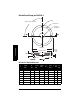
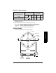
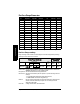

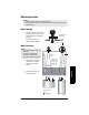
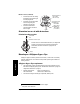
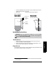
Table Of Contents
- Table of Contents
- SITRANS LR250 Overview
- Specifications
- Installation
- Wiring
- Operating via the handheld programmer
- Operating via SIMATIC PDM
- Functions in SIMATIC PDM
- Quick Start Wizard via SIMATIC PDM
- Changing parameter settings using SIMATIC PDM
- Parameters accessed via pull-down menus
- Operating via AMS Device Manager
- Functions in AMS Device Manager
- Features of AMS Device Manager
- Device Description (DD)
- Configuring a new device
- Startup
- Pull-down menu access
- Device configuration
- Quick Start Wizard via AMS Device Manager
- Maintenance and Diagnostics
- Remaining Device Lifetime [see Remaining Device Lifetime (4.2.) on page 99]
- Remaining Sensor Lifetime [see Remaining Sensor Lifetime (4.3.) on page 102]
- Service Schedule [see Service Schedule (4.4.) on page 105]
- Calibration Schedule [see Calibration Schedule (4.5.) on page 108]
- Electronic Temperature
- Wear (see Wear on page 56)
- Communication
- Security
- Device Diagnostics
- AMS Menu Structure
- Functions in AMS Device Manager
- Parameter Reference
- 1. Quick Start
- 2. Setup
- 3. Diagnostics
- 4. Service
- 5. Communication
- 6. Security
- 7. Language
- Appendix A: Alphabetical Parameter List
- Appendix B: Troubleshooting
- Appendix C: Maintenance
- Appendix D: Technical Reference
- Principles of Operation
- Echo Processing
- Analog Output
- Maximum Process Temperature Chart
- Process Pressure/Temperature derating curves
- Loop power
- Appendix E: Application Examples
- Appendix F: HART Communications
- Appendix G: ATEX Certificates
- Appendix H: Firmware Revision History
- Glossary
- Index
- LCD menu structure

7ML19985JE03 SITRANS LR250 (HART) – INSTRUCTION MANUAL Page 15
mmmmm
Specifications
Flanged Horn dimensions
For flange dimensions see
Raised-Face Flange per EN 1092-1
on page 16 or
Flat-Face
Flange
on page 17
Nominal Horn Size Horn O.D.
Height to sensor
reference point
a)
a)
Height from bottom of horn to sensor reference point as shown: see
Flanged
Horn dimensions
on page 15.
Beam Angle
b)
b)
– 3dB in the direction of the polarization axis (see
Polarization reference point
on page 22 for an illustration).
Measurement
Range
50 mm (2”) 47.8 mm (1.88”) 135.5 mm (5.33”) 15 degrees
20 m (65.6 ft)80 mm (3”) 74.8 mm (2.94”) 168.5 mm (6.63”) 10 degrees
100 mm (4”) 94.8 mm (3.73”) 223.5 mm (8.8”) 8 degrees