
User's Manual
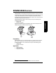
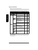
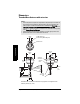
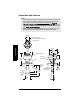
Table Of Contents
- Table of Contents
- SITRANS LR250 Overview
- Specifications
- Installation
- Wiring
- Operating via the handheld programmer
- Operating via SIMATIC PDM
- Functions in SIMATIC PDM
- Quick Start Wizard via SIMATIC PDM
- Changing parameter settings using SIMATIC PDM
- Parameters accessed via pull-down menus
- Operating via AMS Device Manager
- Functions in AMS Device Manager
- Features of AMS Device Manager
- Device Description (DD)
- Configuring a new device
- Startup
- Pull-down menu access
- Device configuration
- Quick Start Wizard via AMS Device Manager
- Maintenance and Diagnostics
- Remaining Device Lifetime [see Remaining Device Lifetime (4.2.) on page 99]
- Remaining Sensor Lifetime [see Remaining Sensor Lifetime (4.3.) on page 102]
- Service Schedule [see Service Schedule (4.4.) on page 105]
- Calibration Schedule [see Calibration Schedule (4.5.) on page 108]
- Electronic Temperature
- Wear (see Wear on page 56)
- Communication
- Security
- Device Diagnostics
- AMS Menu Structure
- Functions in AMS Device Manager
- Parameter Reference
- 1. Quick Start
- 2. Setup
- 3. Diagnostics
- 4. Service
- 5. Communication
- 6. Security
- 7. Language
- Appendix A: Alphabetical Parameter List
- Appendix B: Troubleshooting
- Appendix C: Maintenance
- Appendix D: Technical Reference
- Principles of Operation
- Echo Processing
- Analog Output
- Maximum Process Temperature Chart
- Process Pressure/Temperature derating curves
- Loop power
- Appendix E: Application Examples
- Appendix F: HART Communications
- Appendix G: ATEX Certificates
- Appendix H: Firmware Revision History
- Glossary
- Index
- LCD menu structure

Page 12 SITRANS LR250 (HART) – INSTRUCTION MANUAL 7ML19985JE03
mmmmm
Specifications
Dimensions
Threaded Horn Antenna with extension
See table under
Threaded Horn dimensions
on page 13 for horn height to sensor
reference point (A, B, C, or D).
Notes:
• Process temperature and pressure capabilities are dependent upon information on
the process device tag. Reference drawing listed on the Tag is available on the
product page of our website at www.siemens.com/LR250, under More Info/
Installation drawings/Level Measurement/Installation Drawings/LR250. Additional
information on process connections is available on the Installation Drawings page
under Process Connection Diagrams.
• Signal amplitude increases with horn diameter, so use the largest practical size.
• Optional extensions can be installed below the threads.
threaded cover
enclosure/
electronics
196 mm
(7.7")
154 mm
(6.1")
167 mm
(6.6")
1/2" NPT cable entry
(or alternatively, M20 cable gland)
sensor
ref.
point
retaining
collar
90 mm
(3.5")
159 mm
(6.26")
50 mm
(2.0")
horn
28 mm (1.1")
optional
100 mm (4.0 ")
horn extension
process
device tag
horn
O.D.
A
B
C
D