
User's Manual
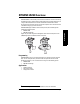
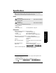
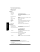
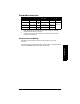
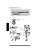
Table Of Contents
- Table of Contents
- SITRANS LR250 Overview
- Specifications
- Installation
- Wiring
- Operating via the handheld programmer
- Operating via SIMATIC PDM
- Functions in SIMATIC PDM
- Quick Start Wizard via SIMATIC PDM
- Changing parameter settings using SIMATIC PDM
- Parameters accessed via pull-down menus
- Operating via AMS Device Manager
- Functions in AMS Device Manager
- Features of AMS Device Manager
- Device Description (DD)
- Configuring a new device
- Startup
- Pull-down menu access
- Device configuration
- Quick Start Wizard via AMS Device Manager
- Maintenance and Diagnostics
- Remaining Device Lifetime [see Remaining Device Lifetime (4.2.) on page 99]
- Remaining Sensor Lifetime [see Remaining Sensor Lifetime (4.3.) on page 102]
- Service Schedule [see Service Schedule (4.4.) on page 105]
- Calibration Schedule [see Calibration Schedule (4.5.) on page 108]
- Electronic Temperature
- Wear (see Wear on page 56)
- Communication
- Security
- Device Diagnostics
- AMS Menu Structure
- Functions in AMS Device Manager
- Parameter Reference
- 1. Quick Start
- 2. Setup
- 3. Diagnostics
- 4. Service
- 5. Communication
- 6. Security
- 7. Language
- Appendix A: Alphabetical Parameter List
- Appendix B: Troubleshooting
- Appendix C: Maintenance
- Appendix D: Technical Reference
- Principles of Operation
- Echo Processing
- Analog Output
- Maximum Process Temperature Chart
- Process Pressure/Temperature derating curves
- Loop power
- Appendix E: Application Examples
- Appendix F: HART Communications
- Appendix G: ATEX Certificates
- Appendix H: Firmware Revision History
- Glossary
- Index
- LCD menu structure

Page 10 SITRANS LR250 (HART) – INSTRUCTION MANUAL 7ML19985JE03
mmmmm
Specifications
Process
•temperature
1)
at process connection
- with FKM O-ring −40 to +200 °C (−40 to +392 °F)
- with FFKM O-ring −20 to +200 °C (−4 to +392 °F)
• pressure (vessel)
1
Refer to
Process Pressure/Temperature derating
curves
on page 136.
Approvals
• General CSA
US/C
, FM, CE
• Radio Europe (R&TTE), FCC, Industry Canada
• Hazardous Intrinsically Safe
2)
(Europe) ATEX II 1G, EEx ia IIC T4
ATEX II 3G, Ex na II T4
ATEX II 1D, EEx tD A20 IP67 T90 °C
(International) IECEx SIR 05.0031X, Ex ia IIC T4,
EX tD A20 IP67 T90 °C
(US/Canada) FM/CSA: (barrier required)
Class I, Div. 1, Groups A, B, C, D
Class II, Div. 1, Groups E, F, G
Class III T4
(Brazil) BR-Ex ia IIC T4 IP67
Non-incendive
3)
(US/Canada) FM/CSA
Class I, Div. 2,
Groups A, B, C, D T5
1)
The specifications apply to the standard horn only. The maximum temperature is
dependent on the process connection, antenna materials, and vessel pressure.
For more detail, or for other configurations, see
Maximum Process Temperature
Chart
on page 135, and
Process Pressure/Temperature derating curves
on page
136.
Note: The device nameplate lists the approvals that apply to your device.
2)
See
Intrinsically Safe wiring
on page 26 for more details.
3)
See
Non-incendive wiring (US/Canada only)
on page 28 for more details.