
User's Manual
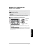
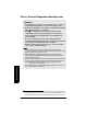
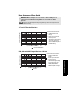
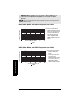
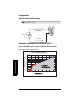
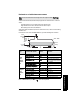
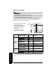
Table Of Contents
- Table of Contents
- SITRANS LR250 Overview
- Specifications
- Installation
- Wiring
- Operating via the handheld programmer
- Operating via SIMATIC PDM
- Functions in SIMATIC PDM
- Quick Start Wizard via SIMATIC PDM
- Changing parameter settings using SIMATIC PDM
- Parameters accessed via pull-down menus
- Operating via AMS Device Manager
- Functions in AMS Device Manager
- Features of AMS Device Manager
- Device Description (DD)
- Configuring a new device
- Startup
- Pull-down menu access
- Device configuration
- Quick Start Wizard via AMS Device Manager
- Maintenance and Diagnostics
- Remaining Device Lifetime [see Remaining Device Lifetime (4.2.) on page 99]
- Remaining Sensor Lifetime [see Remaining Sensor Lifetime (4.3.) on page 102]
- Service Schedule [see Service Schedule (4.4.) on page 105]
- Calibration Schedule [see Calibration Schedule (4.5.) on page 108]
- Electronic Temperature
- Wear (see Wear on page 56)
- Communication
- Security
- Device Diagnostics
- AMS Menu Structure
- Functions in AMS Device Manager
- Parameter Reference
- 1. Quick Start
- 2. Setup
- 3. Diagnostics
- 4. Service
- 5. Communication
- 6. Security
- 7. Language
- Appendix A: Alphabetical Parameter List
- Appendix B: Troubleshooting
- Appendix C: Maintenance
- Appendix D: Technical Reference
- Principles of Operation
- Echo Processing
- Analog Output
- Maximum Process Temperature Chart
- Process Pressure/Temperature derating curves
- Loop power
- Appendix E: Application Examples
- Appendix F: HART Communications
- Appendix G: ATEX Certificates
- Appendix H: Firmware Revision History
- Glossary
- Index
- LCD menu structure

Page 144 SITRANS LR250 (HART) – INSTRUCTION MANUAL 7ML19985JE03
mmmmm
E: Application Examples
Application with Stillpipe
This application is to obtain a level measurement and corresponding 4 to 20 mA output
proportional to the oil level in a fuel storage vessel.
Notes:
• Near Range (2.8.1.) (Blanking) will be set at the factory. Check the Process Device Tag for
specific values.
• Suitable pipe diameters are 40 mm (1.5”) to 100 mm (4”).
• The pipe diameter must be matched with the horn size. Use the largest horn size that will
fit the stillpipe/bypass pipe (see
Dimensions
on page 12).
• See
Mounting on a Stillpipe or Bypass Pipe
on page 22 for installation guidelines.
Parameter
type
Parameter No./Name
Options/
Values
Function
Quick Start
Wizard
Material (1.2.) LIQUID LOW DK
Response Rate (1.3.) MED Medium =1 m/minute
Units (1.4.) M meters
Operation Mode (1.5.) LEVEL
Level is reported as Volume
when a vessel shape is
selected.
Low Calibration Point (1.6.) 5 5 m (16.5 ft)
High Calibration Point (1.7.) 0.5 0.5 m (1.64 ft)
Apply? (Apply changes) (1.8.) YES
Transfers Quick Start settings to
device.
Indepen-
dent
parameters
Propagation Factor (2.8.3.)
a)
a)
The recommended values for the propagation factor and for CLEF range are dependent
on the stillpipe diameter. See
Propagation Factor/Stillpipe Diameter
on page 145 for val-
ues.
0.990
P.F. for a 50 mm (1.96") I.D.
stillpipe
Position Detect (2.8.4.2.) HYBRID
CLEF Range (2.8.4.4.)
a
4.3 4.3 m (14.10 ft)
• Low Calibration Pt. is 5 m (16.5 ft) from
the sensor reference point.
• High Calibration Pt. is 0.5 m (1.65 ft)
from the sensor reference point.
• The stillpipe inside diameter is
50 mm (1.96").
• The maximum rate of filling or
emptying is about 0.1 m (4")/min.
5 m
0.5 m
sensor
reference
point
Low Cal.
Pt.
High
Cal.
Pt.
50 mm I.D.
vent hole