
User's Manual
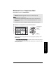
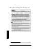
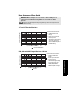
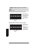
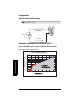
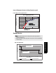
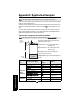
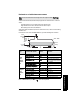
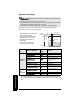
Table Of Contents
- Table of Contents
- SITRANS LR250 Overview
- Specifications
- Installation
- Wiring
- Operating via the handheld programmer
- Operating via SIMATIC PDM
- Functions in SIMATIC PDM
- Quick Start Wizard via SIMATIC PDM
- Changing parameter settings using SIMATIC PDM
- Parameters accessed via pull-down menus
- Operating via AMS Device Manager
- Functions in AMS Device Manager
- Features of AMS Device Manager
- Device Description (DD)
- Configuring a new device
- Startup
- Pull-down menu access
- Device configuration
- Quick Start Wizard via AMS Device Manager
- Maintenance and Diagnostics
- Remaining Device Lifetime [see Remaining Device Lifetime (4.2.) on page 99]
- Remaining Sensor Lifetime [see Remaining Sensor Lifetime (4.3.) on page 102]
- Service Schedule [see Service Schedule (4.4.) on page 105]
- Calibration Schedule [see Calibration Schedule (4.5.) on page 108]
- Electronic Temperature
- Wear (see Wear on page 56)
- Communication
- Security
- Device Diagnostics
- AMS Menu Structure
- Functions in AMS Device Manager
- Parameter Reference
- 1. Quick Start
- 2. Setup
- 3. Diagnostics
- 4. Service
- 5. Communication
- 6. Security
- 7. Language
- Appendix A: Alphabetical Parameter List
- Appendix B: Troubleshooting
- Appendix C: Maintenance
- Appendix D: Technical Reference
- Principles of Operation
- Echo Processing
- Analog Output
- Maximum Process Temperature Chart
- Process Pressure/Temperature derating curves
- Loop power
- Appendix E: Application Examples
- Appendix F: HART Communications
- Appendix G: ATEX Certificates
- Appendix H: Firmware Revision History
- Glossary
- Index
- LCD menu structure

7ML19985JE03 SITRANS LR250 (HART) – INSTRUCTION MANUAL Page 141
mmmmm
D: Technical Reference
Curve 2 (Flameproof, Increased Safety, Explosion-proof)
Loop Voltage versus Loop Resistance
Startup Behavior
Notes:
• SITRANS LR250 is designed to start reliably with a power supply capable of
delivering at least 25 mA.
• When connected to a power supply with a current limit of < 25 mA, the LR250 may
not start reliably.
Power Supply Requirements
0
50
100
150
200
250
300
350
400
15 20 25 30
Loop Voltage - V
L
(Source Voltage)
Loop Resistance - R
L
(30.0V, 375 ohms)
RL = 14.88 * VL - 71.43
(21.6V, 250 ohms)
(18.2V, 0 ohms)
RL = 73.53 * VL - 1338.24
Power Supply Requirements
Loop Voltage – V
L
Loop Resistance – R
L
ALLOWABLE
OPERATING AREA
0
5
10
15
20
25
30
35
40
0 2 4 6 8 10 12 14 16 18 20 22 24 26 28 30 32 34
Time (seconds)
Current (mA)
No Current Limit Current Lim ited Power Supply
Typical Startup Current
Time (seconds)
Current (mA)
Loop Power Supply
without Current Limit
Loop Power Supply with
25 mA Current Limit
Current-limited powerNo current limit