
User's Manual
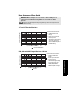
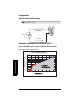
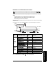
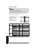
Table Of Contents
- Table of Contents
- SITRANS LR250 Overview
- Specifications
- Installation
- Wiring
- Operating via the handheld programmer
- Operating via SIMATIC PDM
- Functions in SIMATIC PDM
- Quick Start Wizard via SIMATIC PDM
- Changing parameter settings using SIMATIC PDM
- Parameters accessed via pull-down menus
- Operating via AMS Device Manager
- Functions in AMS Device Manager
- Features of AMS Device Manager
- Device Description (DD)
- Configuring a new device
- Startup
- Pull-down menu access
- Device configuration
- Quick Start Wizard via AMS Device Manager
- Maintenance and Diagnostics
- Remaining Device Lifetime [see Remaining Device Lifetime (4.2.) on page 99]
- Remaining Sensor Lifetime [see Remaining Sensor Lifetime (4.3.) on page 102]
- Service Schedule [see Service Schedule (4.4.) on page 105]
- Calibration Schedule [see Calibration Schedule (4.5.) on page 108]
- Electronic Temperature
- Wear (see Wear on page 56)
- Communication
- Security
- Device Diagnostics
- AMS Menu Structure
- Functions in AMS Device Manager
- Parameter Reference
- 1. Quick Start
- 2. Setup
- 3. Diagnostics
- 4. Service
- 5. Communication
- 6. Security
- 7. Language
- Appendix A: Alphabetical Parameter List
- Appendix B: Troubleshooting
- Appendix C: Maintenance
- Appendix D: Technical Reference
- Principles of Operation
- Echo Processing
- Analog Output
- Maximum Process Temperature Chart
- Process Pressure/Temperature derating curves
- Loop power
- Appendix E: Application Examples
- Appendix F: HART Communications
- Appendix G: ATEX Certificates
- Appendix H: Firmware Revision History
- Glossary
- Index
- LCD menu structure

7ML19985JE03 SITRANS LR250 (HART) – INSTRUCTION MANUAL Page 135
mmmmm
D: Technical Reference
Maximum Process Temperature Chart
Flange Adapter versions of SITRANS LR250
.
Where the chart does not apply, please use your own judgement regarding the use of
SITRANS LR250.
See Current Internal Temperature (3.2.1.) on page 98 to monitor the Internal Temperature.
If the internal temperature exceeds the maximum allowable limit, a sun shield or a longer
nozzle may be required.
WARNING: Internal temperature must not exceed 80 °C (176 °F).
Notes:
• The chart below is for guidance only.
• The chart does not represent every possible process connection arrangement. For
example, it will NOT apply if you are mounting SITRANS LR250 directly on a metallic
vessel surface.
• The chart does not take into consideration heating from direct sunshine exposure.
process
temperature
Ambient Temperature (
o
C)
Process Temperature (
o
C)
Maximum Process Temperatures versus allowable ambient
ambient
temperature
internal enclosure
temperature
process
temperature