
User's Manual
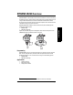
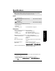
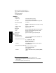
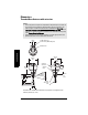
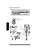
Table Of Contents
- Table of Contents
- SITRANS LR250 Overview
- Specifications
- Installation
- Wiring
- Operating via the handheld programmer
- Operating via SIMATIC PDM
- Functions in SIMATIC PDM
- Quick Start Wizard via SIMATIC PDM
- Changing parameter settings using SIMATIC PDM
- Parameters accessed via pull-down menus
- Operating via AMS Device Manager
- Functions in AMS Device Manager
- Features of AMS Device Manager
- Device Description (DD)
- Configuring a new device
- Startup
- Pull-down menu access
- Device configuration
- Quick Start Wizard via AMS Device Manager
- Maintenance and Diagnostics
- Remaining Device Lifetime [see Remaining Device Lifetime (4.2.) on page 99]
- Remaining Sensor Lifetime [see Remaining Sensor Lifetime (4.3.) on page 102]
- Service Schedule [see Service Schedule (4.4.) on page 105]
- Calibration Schedule [see Calibration Schedule (4.5.) on page 108]
- Electronic Temperature
- Wear (see Wear on page 56)
- Communication
- Security
- Device Diagnostics
- AMS Menu Structure
- Functions in AMS Device Manager
- Parameter Reference
- 1. Quick Start
- 2. Setup
- 3. Diagnostics
- 4. Service
- 5. Communication
- 6. Security
- 7. Language
- Appendix A: Alphabetical Parameter List
- Appendix B: Troubleshooting
- Appendix C: Maintenance
- Appendix D: Technical Reference
- Principles of Operation
- Echo Processing
- Analog Output
- Maximum Process Temperature Chart
- Process Pressure/Temperature derating curves
- Loop power
- Appendix E: Application Examples
- Appendix F: HART Communications
- Appendix G: ATEX Certificates
- Appendix H: Firmware Revision History
- Glossary
- Index
- LCD menu structure

Page 8 SITRANS LR250 (HART) – INSTRUCTION MANUAL 7ML19985JE03
mmmmm
Specifications
Dielectric constant of material measured
• dK > 1.6 (horn and application dependent
1)
)
Memory:
• non-volatile EEPROM
• no battery required.
Interface
Analog output
• signal range 4 to 20 mA (±
0.02 mA accuracy)
upper limit 20 to 23 mA adjustable
• fail signal 3.6 mA to 23 mA (see
Fail-safe Mode
on page 134 for
more details)
Communication: HART
• Load 230 to 600 Ω, 230 to 500 Ω when connecting a coupling
module
• Max. Line Length multi-wire: ≤ 1500 m (4921 ft)
• Protocol HART, Version 5.1
Configuration
• remote Siemens SIMATIC PDM or AMS Device Manager (PC)
• local Siemens infrared handheld programmer, or HART
handheld communicator
Display (local)
2)
graphic LCD, with bar graph representing level
Mechanical
Process Connections:
• threaded connection 1.5” or 2" NPT (ASME B1.20.1), BSPT (EN 10226-1)
3)
or
G (BS EN ISO 228-1)
• flange connection (flat-face)
2", 3", 4" (ASME 150 lb, 300 lb)
50, 80, 100 mm (PN 16, PN 40)
50A, 80A, 100A (JIS 10K)
materials 316 L /1.4404 or 316 L /1.4435 stainless steel, optional
Alloy N06022/2.4602
• flange connection (raised face)
50, 80, 100 mm (PN 10/16, PN 25/40)
150 mm (PN 10/16,PN 25/40)
per EN 1092-1 B1
materials 1.4404 or 1.4435 stainless steel, optional Alloy N06022/
2.4602
1)
For 1.5" (40 mm) horn the dK is limited to 3 unless a stillpipe is used.
2)
Display quality will be degraded in temperatures below –25 °C (–13 °F) and above
+65 °C (+149 °F).
3)
For use with 1.5" (40 mm) horn antennas only.