
User's Manual
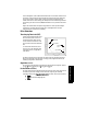
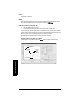
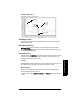
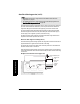
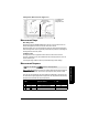
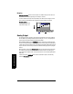
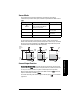
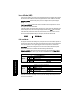
Table Of Contents
- Table of Contents
- SITRANS LR250 Overview
- Specifications
- Installation
- Wiring
- Operating via the handheld programmer
- Operating via SIMATIC PDM
- Functions in SIMATIC PDM
- Quick Start Wizard via SIMATIC PDM
- Changing parameter settings using SIMATIC PDM
- Parameters accessed via pull-down menus
- Operating via AMS Device Manager
- Functions in AMS Device Manager
- Features of AMS Device Manager
- Device Description (DD)
- Configuring a new device
- Startup
- Pull-down menu access
- Device configuration
- Quick Start Wizard via AMS Device Manager
- Maintenance and Diagnostics
- Remaining Device Lifetime [see Remaining Device Lifetime (4.2.) on page 99]
- Remaining Sensor Lifetime [see Remaining Sensor Lifetime (4.3.) on page 102]
- Service Schedule [see Service Schedule (4.4.) on page 105]
- Calibration Schedule [see Calibration Schedule (4.5.) on page 108]
- Electronic Temperature
- Wear (see Wear on page 56)
- Communication
- Security
- Device Diagnostics
- AMS Menu Structure
- Functions in AMS Device Manager
- Parameter Reference
- 1. Quick Start
- 2. Setup
- 3. Diagnostics
- 4. Service
- 5. Communication
- 6. Security
- 7. Language
- Appendix A: Alphabetical Parameter List
- Appendix B: Troubleshooting
- Appendix C: Maintenance
- Appendix D: Technical Reference
- Principles of Operation
- Echo Processing
- Analog Output
- Maximum Process Temperature Chart
- Process Pressure/Temperature derating curves
- Loop power
- Appendix E: Application Examples
- Appendix F: HART Communications
- Appendix G: ATEX Certificates
- Appendix H: Firmware Revision History
- Glossary
- Index
- LCD menu structure

7ML19985JE03 SITRANS LR250 (HART) – INSTRUCTION MANUAL Page 131
mmmmm
D: Technical Reference
Measurement Range
Near Range (2.8.1.)
Near Range programs SITRANS LR250 to ignore the zone in front of the antenna. The
default blanking distance is 50 mm (1.97") from end of horn antenna.
Near Range allows you to increase the blanking value from its factory default. But Auto
False Echo Suppression (2.8.7.1.) is generally recommended in preference to extending the
blanking distance from factory values.
Far Range (2.8.2.)
Far Range can be used in applications where the base of the vessel is conical or
parabolic. A reliable echo may be available below the vessel empty distance, due to an
indirect reflection path.
Increasing Far Range to 30% or 40% can provide stable empty vessel readings.
Measurement Response
Response Rate (2.4.1.) limits the maximum rate at which the display and output respond to
changes in the measurement. There are three preset options: slow, medium, and fast.
Once the real process fill/empty rate (m/s by default) is established, a response rate can
be selected that is slightly higher than the application rate. Response Rate automatically
adjusts the filters that affect the output response rate.
Note: Units are defined in Units (2.2.1.) and are in meters by default.
Response Rate
(2.4.1.)
Fill Rate (2.4.2.)/
Empty rate (2.4.3.)
Damping Filter
(2.2.4.)
* Slow 0.1 m/min (0.32 ft/min) 10 s
Medium 1.0 m/min (3.28 ft/min) 10 s
Fast 10.0 m/min (32.8 ft/min) 0 s
Example after Auto False Echo Suppression
learned
TVT
material
echo
false echo
echo
marker
Auto False Echo
Suppression
Range set to 2 m
Auto False Echo
Suppression Range
default
TVT