
User's Manual
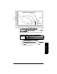
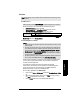
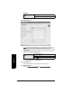
Table Of Contents
- Table of Contents
- SITRANS LR250 Overview
- Specifications
- Installation
- Wiring
- Operating via the handheld programmer
- Operating via SIMATIC PDM
- Functions in SIMATIC PDM
- Quick Start Wizard via SIMATIC PDM
- Changing parameter settings using SIMATIC PDM
- Parameters accessed via pull-down menus
- Operating via AMS Device Manager
- Functions in AMS Device Manager
- Features of AMS Device Manager
- Device Description (DD)
- Configuring a new device
- Startup
- Pull-down menu access
- Device configuration
- Quick Start Wizard via AMS Device Manager
- Maintenance and Diagnostics
- Remaining Device Lifetime [see Remaining Device Lifetime (4.2.) on page 99]
- Remaining Sensor Lifetime [see Remaining Sensor Lifetime (4.3.) on page 102]
- Service Schedule [see Service Schedule (4.4.) on page 105]
- Calibration Schedule [see Calibration Schedule (4.5.) on page 108]
- Electronic Temperature
- Wear (see Wear on page 56)
- Communication
- Security
- Device Diagnostics
- AMS Menu Structure
- Functions in AMS Device Manager
- Parameter Reference
- 1. Quick Start
- 2. Setup
- 3. Diagnostics
- 4. Service
- 5. Communication
- 6. Security
- 7. Language
- Appendix A: Alphabetical Parameter List
- Appendix B: Troubleshooting
- Appendix C: Maintenance
- Appendix D: Technical Reference
- Principles of Operation
- Echo Processing
- Analog Output
- Maximum Process Temperature Chart
- Process Pressure/Temperature derating curves
- Loop power
- Appendix E: Application Examples
- Appendix F: HART Communications
- Appendix G: ATEX Certificates
- Appendix H: Firmware Revision History
- Glossary
- Index
- LCD menu structure

7ML19985JE03 SITRANS LR250 (HART) – INSTRUCTION MANUAL Page 97
mmmmm
Parameters
To use TVT shaper via SIMATIC PDM:
a) Go to Level Meter > Setup > Signal Processing > TVT setup > Shaper
Mode and select On.
b) Open the menu Device – Echo Profile Utilities and click on TVT Shaper. For
more detail see page 51.
To use TVT shaper via LUI (local user interface):
a) Go to Shaper Mode (2.8.7.4.) and select On.
b) Go to TVT Breakpoint 1-9 (2.8.8.1.).
c) Open Shaper 1 and enter the TVT Offset value (between –50 and 50).
d) Go to the next Shaper point and repeat steps c) and d) till all desired
breakpoint values have been entered.
2.8.8.1. TVT Breakpoint 1-9
2.8.8.2. TVT Breakpoint 10-18
2.8.8.3. TVT Breakpoint 19-27
2.8.8.4. TVT Breakpoint 28-36
2.8.8.5. TVT Breakpoint 37-40
2.8.9. Measured Values
Read only. Allows you to view measured values for diagnostic purposes
To access measured values via SIMATIC PDM:
Open the menu View – Process Variables.
2.8.9.1. Level Measurement
The value for level.
2.8.9.2. Space Measurement
The value for space.
2.8.9.3. Distance Measurement
The value for distance.
2.8.9.4. Volume Measurement
The value for volume.
Values
Range: –50 to 50 dB
Default: 0 dB
Values
Range: –50 to 50 dB
Default: 0 dB
Values
Range: –50 to 50 dB
Default: 0 dB
Values
Range: –50 to 50 dB
Default: 0 dB
Values
Range: –50 to 50 dB
Default: 0 dB