
User's Manual
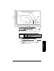
Table Of Contents
- Table of Contents
- SITRANS LR250 Overview
- Specifications
- Installation
- Wiring
- Operating via the handheld programmer
- Operating via SIMATIC PDM
- Functions in SIMATIC PDM
- Quick Start Wizard via SIMATIC PDM
- Changing parameter settings using SIMATIC PDM
- Parameters accessed via pull-down menus
- Operating via AMS Device Manager
- Functions in AMS Device Manager
- Features of AMS Device Manager
- Device Description (DD)
- Configuring a new device
- Startup
- Pull-down menu access
- Device configuration
- Quick Start Wizard via AMS Device Manager
- Maintenance and Diagnostics
- Remaining Device Lifetime [see Remaining Device Lifetime (4.2.) on page 99]
- Remaining Sensor Lifetime [see Remaining Sensor Lifetime (4.3.) on page 102]
- Service Schedule [see Service Schedule (4.4.) on page 105]
- Calibration Schedule [see Calibration Schedule (4.5.) on page 108]
- Electronic Temperature
- Wear (see Wear on page 56)
- Communication
- Security
- Device Diagnostics
- AMS Menu Structure
- Functions in AMS Device Manager
- Parameter Reference
- 1. Quick Start
- 2. Setup
- 3. Diagnostics
- 4. Service
- 5. Communication
- 6. Security
- 7. Language
- Appendix A: Alphabetical Parameter List
- Appendix B: Troubleshooting
- Appendix C: Maintenance
- Appendix D: Technical Reference
- Principles of Operation
- Echo Processing
- Analog Output
- Maximum Process Temperature Chart
- Process Pressure/Temperature derating curves
- Loop power
- Appendix E: Application Examples
- Appendix F: HART Communications
- Appendix G: ATEX Certificates
- Appendix H: Firmware Revision History
- Glossary
- Index
- LCD menu structure

Page 96 SITRANS LR250 (HART) – INSTRUCTION MANUAL 7ML19985JE03
mmmmm
Parameters
2.8.7.2. Auto False Echo Suppression Range
Specifies the range within which Learned TVT is used (see Auto False Echo
Suppression (2.8.7.1.) on page 130 for more detail).
a) Calculate range according to Auto False Echo Suppression (2.8.7.1.)
steps a) and b).
b) Press RIGHT arrow to open Edit mode.
c) Enter the new value and press RIGHT arrow to accept it.
d) Set Auto False Echo Suppression (2.8.7.1.).
2.8.7.3. Hover Level
Defines how high the TVT (Time Varying Threshold) is placed above the
noise floor of the echo profile, as a percentage of the difference between
the peak of the largest echo in the profile and the noise floor. See Before
Auto False Echo Suppression on page 94 for an illustration.
When the device is located in the center of the vessel, the TVT hover level
may be lowered to increase the confidence level of the largest echo.
2.8.7.4. Shaper Mode
Enables/disables the TVT shaper.
2.8.8. TVT shaper
Adjusts the TVT (Time Varying Threshold) at a specified range (breakpoint on
the TVT). This allows you to reshape the TVT to avoid unwanted echoes. There
are 40 breakpoints arranged in 5 groups. (We recommend using SIMATIC PDM
to access this feature.)
Values
Range: 0.00 to 20.00 m
Default: 1.0 0 m
Related parameters Units (1.4.)
Values
Range: 0 to 100%
Default: 40%
Options
ON
*OFF
Notes:
• The range is –100 to 100 bits. With 2 bits per dB this gives a range of –50 to
50 dB.
• Shaper Mode (2.8.7.4.) must be turned ON in order for TVT shaper points to
be transferred