User's Manual
Table Of Contents
- SITRANS LR250 (PROFIBUS PA)
- Legal information
- Table of contents
- 1 Introduction
- 2 Safety notes
- 3 Description
- 4 Installing/mounting
- 5 Connecting
- 6 Commissioning
- 7 Remote operation
- 8 Parameter reference
- 9 Service and maintenance
- 10 Diagnosing and troubleshooting
- 11 Technical data
- 12 Dimension drawings
- 12.1 Threaded horn antenna
- 12.2 Threaded horn antenna with extension
- 12.3 Flanged horn antenna
- 12.4 Flanged horn antenna with extension
- 12.5 Flanged encapsulated antenna (2"/DN50/50A sizes only)
- 12.6 Flanged encapsulated antenna (3"/DN80/80A sizes and larger)
- 12.7 Threaded PVDF antenna
- 12.8 Threaded connection markings
- 12.9 Raised-Face flange per EN 1092-1 for flanged horn antenna
- 12.10 Raised-Face flange per EN 1092-1 for flanged encapsulated antenna
- 12.11 Flat-Face flange
- 12.12 Process connection tag (pressure rated versions)
- A Appendix A: Technical reference
- B Appendix B: PROFIBUS PA profile structure
- C Appendix C: Communications via PROFIBUS
- D Appendix D: Certificates and Support
- 13 List of abbreviations
- 14 LCD menu structure
- Glossary
- Index

Remote operation
7.1 Operating via SIMATIC PDM
SITRANS LR250 (PROFIBUS PA)
80 Operating Instructions, 01/2014, A5E32221386-AB
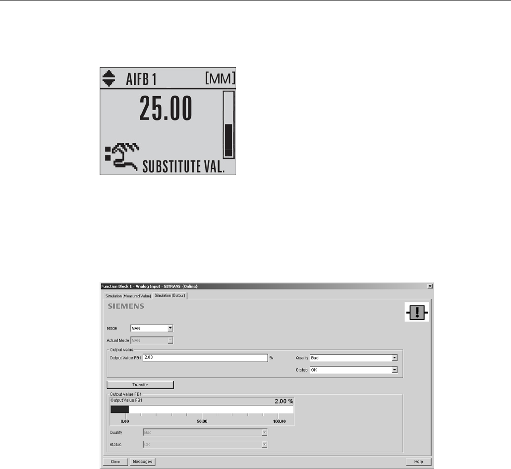
4. The Output value from the desired function block is displayed in PDM, and the LCD displays
the substitute value. See Simulate Output below, to set the output mode.
5. After simulation is complete, disable simulation and click on
Transfer
.
Simulate output
1. Open the menu
Device – Simulation
, select function block 1 or 2, and click on the tab
Simulation (Output).
2. Select Manual Mode (from options AUTO, Manual, or Out of Service) and click on
Transfer
.
3. Enter simulated value and click on
Transfer
.
4. After simulation is complete, return to Simulate Output, reselect AUTO mode, and click on
Transfer
.


