User's Manual
Table Of Contents
- SITRANS LR250 (PROFIBUS PA)
- Legal information
- Table of contents
- 1 Introduction
- 2 Safety notes
- 3 Description
- 4 Installing/mounting
- 5 Connecting
- 6 Commissioning
- 7 Remote operation
- 8 Parameter reference
- 9 Service and maintenance
- 10 Diagnosing and troubleshooting
- 11 Technical data
- 12 Dimension drawings
- 12.1 Threaded horn antenna
- 12.2 Threaded horn antenna with extension
- 12.3 Flanged horn antenna
- 12.4 Flanged horn antenna with extension
- 12.5 Flanged encapsulated antenna (2"/DN50/50A sizes only)
- 12.6 Flanged encapsulated antenna (3"/DN80/80A sizes and larger)
- 12.7 Threaded PVDF antenna
- 12.8 Threaded connection markings
- 12.9 Raised-Face flange per EN 1092-1 for flanged horn antenna
- 12.10 Raised-Face flange per EN 1092-1 for flanged encapsulated antenna
- 12.11 Flat-Face flange
- 12.12 Process connection tag (pressure rated versions)
- A Appendix A: Technical reference
- B Appendix B: PROFIBUS PA profile structure
- C Appendix C: Communications via PROFIBUS
- D Appendix D: Certificates and Support
- 13 List of abbreviations
- 14 LCD menu structure
- Glossary
- Index

Commissioning
6.1 Operating via the handheld programmer
SITRANS LR250 (PROFIBUS PA)
36 Operating Instructions, 01/2014, A5E32221386-AB
6.1.2.1
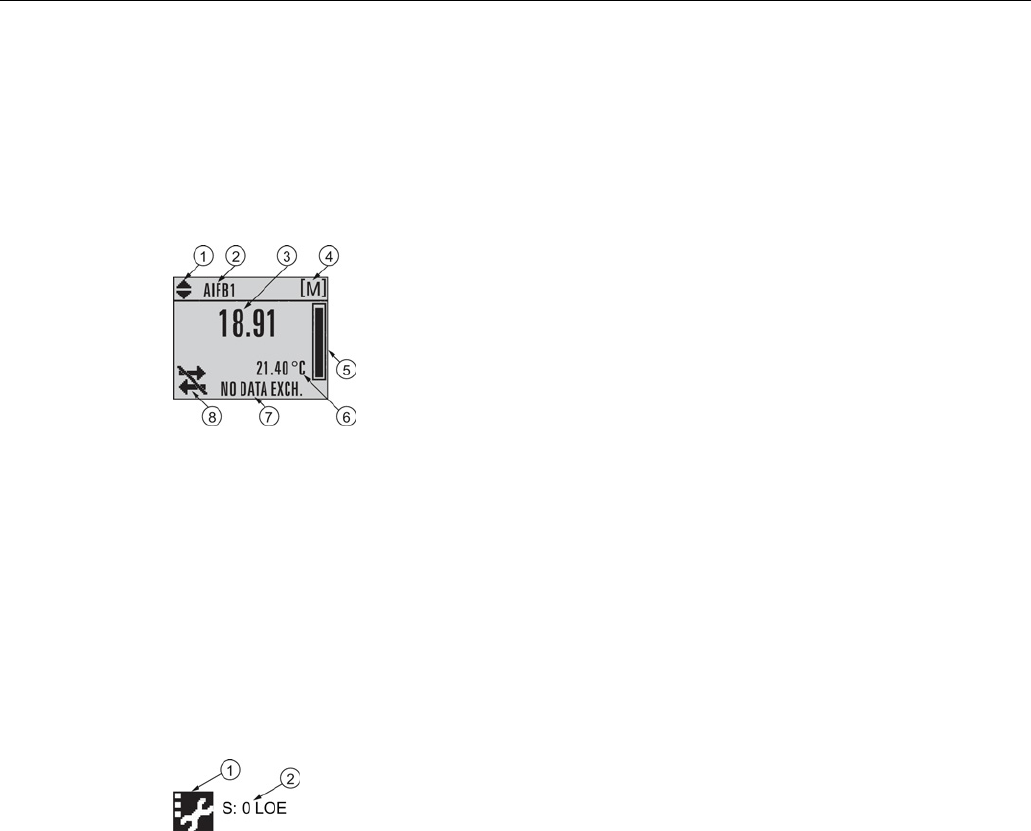
The LCD display
Measurement mode display
Normal operation
①
toggle indicator
a)
for AIFB 1 or AIFB 2
⑤
bar graph indicates level
②
identifies which AIFB is source of
displayed value
⑥
secondary region indicates on request
b)
electronics
temperature, echo confidence, or distance
③
measured value (level, space, distance, or
volume)
⑦
text area displays status messages
④
units
⑧
device status indicator
a)
Press
UP
and
DOWN
arrow to switch.
b)
In response to a key press request. For details, see Programming (Page 39).
Fault present
①
service required icon appears
②
text area displays a fault code and an error message


