
User's Manual
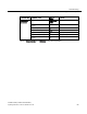
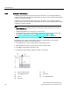
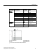
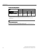
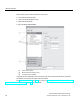
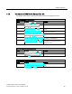
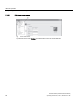
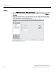
Table Of Contents
- SITRANS LR250 (FOUNDATION FIELDBUS)
- Legal information
- Table of contents
- 1 Introduction
- 2 Safety notes
- 3 Description
- 4 Installing/mounting
- 5 Connecting
- 6 Commissioning
- 7 Remote operation
- 7.1 Operating via AMS Device Manager
- 7.1.1 Functions in AMS Device Manager
- 7.1.2 Key features of AMS Device Manager Rev. 9.0
- 7.1.3 Adding a new device
- 7.1.4 Master Reset
- 7.1.5 Scan Device
- 7.1.6 Sensor calibration
- 7.1.7 Configuring a new device
- 7.1.8 Changing parameter settings using AMS Device Manager
- 7.1.9 Configure/Setup (Level Transducer Block-LTB)
- 7.1.10 Configure/Setup (Liquid Crystal Display Block-LCD)
- 7.1.11 Configure/Setup (Diagnostic Transducer Block-DIAG)
- 7.1.12 Configure/Setup (Resource Block - RESOURCE)
- 7.1.13 Device Diagnostics (Level Transducer Block - LTB)
- 7.1.14 Device Diagnostics (Liquid Crystal Display Block - LCD)
- 7.1.15 Device Diagnostics (Diagnostic Transducer Block - DIAG)
- 7.1.16 Device Diagnostics (Resource Block - RESOURCE)
- 7.1.17 Process Variables (Level Transducer Block - LTB)
- 7.1.18 Password Protection
- 7.1.19 AMS menu structure
- 7.1 Operating via AMS Device Manager
- 8 Parameter reference
- 9 Service and maintenance
- 10 Diagnosing and troubleshooting
- 11 Technical data
- 12 Dimension drawings
- 12.1 Threaded horn antenna
- 12.2 Threaded horn antenna with extension
- 12.3 Flanged horn antenna
- 12.4 Flanged horn antenna with extension
- 12.5 Flanged encapsulated antenna (2"/DN50/50A sizes only)
- 12.6 Flanged encapsulated antenna (3"/DN80/80A sizes and larger)
- 12.7 Threaded PVDF antenna
- 12.8 Threaded connection markings
- 12.9 Raised-Face flange per EN 1092-1 for flanged horn antenna
- 12.10 Raised-Face flange per EN 1092-1 for flanged encapsulated antenna
- 12.11 Flat-Face flange
- 12.12 Process connection tag (pressure rated versions)
- A Appendix A: Technical reference
- B Appendix B: Communications via Foundation Fieldbus
- C Appendix C: Certificates and support
- 13 List of abbreviations
- 14 LCD menu structure
- Glossary
- Index

Commissioning
6.2 Application examples
SITRANS LR250 (FOUNDATION FIELDBUS)
62 Operating Instructions, 01/2014, A5E32221411-AB
Propagation Factor/Stillpipe Diameter
Values
Range
0.3 to 1.0 depending on pipe size
Default
1.0000
Nominal Pipe Size
a)
40 mm (1.5")
50 mm (2")
80 mm (3")
100 mm (4")
Propagation Factor
0.9844
0.988
0.9935
0.9965
CLEF Range (2.5.7.4.) settings
Low
calibration
point - 700
mm (2.29 ft)
b)
Low
calibration
point - 700
mm (2.29 ft)
b)
Low
calibration
point - 1000
mm (3.28 ft)
b)
Low
calibration
point - 1000
mm (3.28 ft)
b)
a)
Since pipe dimensions may vary slightly, the propagation factor may also vary.
b)
CLEF range covers the whole measurement range except first 700 or 1000 mm from sensor
reference point
Note
Flanged encapsulated antenna
For Flanged encapsulated antenna (7ML5432) match the process connection size to the
pipe diameter.
For example, DN 80/3" flange to DN 80/3" pipe.