
User's Manual
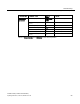
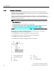
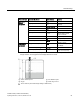
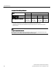
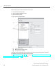
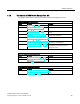
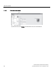
Table Of Contents
- SITRANS LR250 (FOUNDATION FIELDBUS)
- Legal information
- Table of contents
- 1 Introduction
- 2 Safety notes
- 3 Description
- 4 Installing/mounting
- 5 Connecting
- 6 Commissioning
- 7 Remote operation
- 7.1 Operating via AMS Device Manager
- 7.1.1 Functions in AMS Device Manager
- 7.1.2 Key features of AMS Device Manager Rev. 9.0
- 7.1.3 Adding a new device
- 7.1.4 Master Reset
- 7.1.5 Scan Device
- 7.1.6 Sensor calibration
- 7.1.7 Configuring a new device
- 7.1.8 Changing parameter settings using AMS Device Manager
- 7.1.9 Configure/Setup (Level Transducer Block-LTB)
- 7.1.10 Configure/Setup (Liquid Crystal Display Block-LCD)
- 7.1.11 Configure/Setup (Diagnostic Transducer Block-DIAG)
- 7.1.12 Configure/Setup (Resource Block - RESOURCE)
- 7.1.13 Device Diagnostics (Level Transducer Block - LTB)
- 7.1.14 Device Diagnostics (Liquid Crystal Display Block - LCD)
- 7.1.15 Device Diagnostics (Diagnostic Transducer Block - DIAG)
- 7.1.16 Device Diagnostics (Resource Block - RESOURCE)
- 7.1.17 Process Variables (Level Transducer Block - LTB)
- 7.1.18 Password Protection
- 7.1.19 AMS menu structure
- 7.1 Operating via AMS Device Manager
- 8 Parameter reference
- 9 Service and maintenance
- 10 Diagnosing and troubleshooting
- 11 Technical data
- 12 Dimension drawings
- 12.1 Threaded horn antenna
- 12.2 Threaded horn antenna with extension
- 12.3 Flanged horn antenna
- 12.4 Flanged horn antenna with extension
- 12.5 Flanged encapsulated antenna (2"/DN50/50A sizes only)
- 12.6 Flanged encapsulated antenna (3"/DN80/80A sizes and larger)
- 12.7 Threaded PVDF antenna
- 12.8 Threaded connection markings
- 12.9 Raised-Face flange per EN 1092-1 for flanged horn antenna
- 12.10 Raised-Face flange per EN 1092-1 for flanged encapsulated antenna
- 12.11 Flat-Face flange
- 12.12 Process connection tag (pressure rated versions)
- A Appendix A: Technical reference
- B Appendix B: Communications via Foundation Fieldbus
- C Appendix C: Certificates and support
- 13 List of abbreviations
- 14 LCD menu structure
- Glossary
- Index
Commissioning
6.2 Application examples
SITRANS LR250 (FOUNDATION FIELDBUS)
Operating Instructions, 01/2014, A5E32221411-AB
61
Parameter type
Parameter No./Name
Options/Values
Function
Quick Start
Wizard
parameters
Introduction
NEXT
Continue with Wizard.
Language
NEXT
Continue with current
language.
Material
LIQUID LOW DK
Response Rate
MED
Medium =1 m/minute
Units
M
meters
Operating mode
LEVEL
Level is reported as
Volume when a vessel
shape is selected.
Low Calibration Point
5
5 m (16.4 ft)
High Calibration Point
0.5
0.5 m (1.64 ft)
Wizard Complete
FINISH
Transfers Quick Start
settings to device.
Independent
parameters
Propagation Factor (2.5.3.)
a)
0.988
P.F. for a 50 mm (1.96")
I.D. stillpipe
Position Detect (2.5.7.2.)
HYBRID
CLEF Range (2.5.7.4.)
a)
4.3 Low calibration point -
0.7 m = 4.3 m (14.1 ft)
a)
The recommended values for the propagation factor and for CLEF range are dependent on the
stillpipe diameter. See Propagation Factor/Stillpipe Diameter for values.
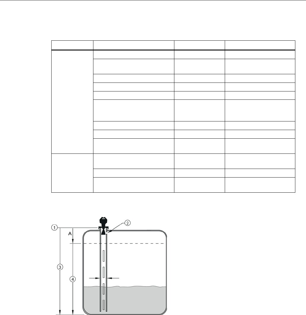
①
sensor reference point
③
low calibration point
②
air gap
④
CLEF range 2.5.7.4.
A
700 or 1000 mm (see CLEF Range settings in table below)