
User's Manual
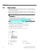
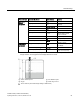
Table Of Contents
- SITRANS LR250 (FOUNDATION FIELDBUS)
- Legal information
- Table of contents
- 1 Introduction
- 2 Safety notes
- 3 Description
- 4 Installing/mounting
- 5 Connecting
- 6 Commissioning
- 7 Remote operation
- 7.1 Operating via AMS Device Manager
- 7.1.1 Functions in AMS Device Manager
- 7.1.2 Key features of AMS Device Manager Rev. 9.0
- 7.1.3 Adding a new device
- 7.1.4 Master Reset
- 7.1.5 Scan Device
- 7.1.6 Sensor calibration
- 7.1.7 Configuring a new device
- 7.1.8 Changing parameter settings using AMS Device Manager
- 7.1.9 Configure/Setup (Level Transducer Block-LTB)
- 7.1.10 Configure/Setup (Liquid Crystal Display Block-LCD)
- 7.1.11 Configure/Setup (Diagnostic Transducer Block-DIAG)
- 7.1.12 Configure/Setup (Resource Block - RESOURCE)
- 7.1.13 Device Diagnostics (Level Transducer Block - LTB)
- 7.1.14 Device Diagnostics (Liquid Crystal Display Block - LCD)
- 7.1.15 Device Diagnostics (Diagnostic Transducer Block - DIAG)
- 7.1.16 Device Diagnostics (Resource Block - RESOURCE)
- 7.1.17 Process Variables (Level Transducer Block - LTB)
- 7.1.18 Password Protection
- 7.1.19 AMS menu structure
- 7.1 Operating via AMS Device Manager
- 8 Parameter reference
- 9 Service and maintenance
- 10 Diagnosing and troubleshooting
- 11 Technical data
- 12 Dimension drawings
- 12.1 Threaded horn antenna
- 12.2 Threaded horn antenna with extension
- 12.3 Flanged horn antenna
- 12.4 Flanged horn antenna with extension
- 12.5 Flanged encapsulated antenna (2"/DN50/50A sizes only)
- 12.6 Flanged encapsulated antenna (3"/DN80/80A sizes and larger)
- 12.7 Threaded PVDF antenna
- 12.8 Threaded connection markings
- 12.9 Raised-Face flange per EN 1092-1 for flanged horn antenna
- 12.10 Raised-Face flange per EN 1092-1 for flanged encapsulated antenna
- 12.11 Flat-Face flange
- 12.12 Process connection tag (pressure rated versions)
- A Appendix A: Technical reference
- B Appendix B: Communications via Foundation Fieldbus
- C Appendix C: Certificates and support
- 13 List of abbreviations
- 14 LCD menu structure
- Glossary
- Index
Commissioning
6.2 Application examples
SITRANS LR250 (FOUNDATION FIELDBUS)
60 Operating Instructions, 01/2014, A5E32221411-AB
6.2.3
Application with stillpipe
A stillpipe is recommended for products with a dK of less than 3, or if extremely turbulent or
vortex conditions exist. This mounting arrangement can also be used to provide optimum signal
conditions on foaming materials.
A stillpipe is recommended for products with a dK of less than 3, or if extremely turbulent or
vortex conditions exist. This mounting arrangement can also be used to provide optimum signal
conditions on foaming materials.
Note
•
Near Range (2.5.1.)
(Blanking) will be set at the factory. Check the process connection
tag for specific values.
•
Suitable pipe diameters are 40 mm (1.5") to 100 mm (4").
•
The pipe diameter must be matched with the antenna size. Use the largest antenna size
that will fit the stillpipe/bypass pipe. See
Dimension drawings (Page 205).
•
See Mounting on a Stillpipe or Bypass Pipe (Page 20) for installation guidelines.
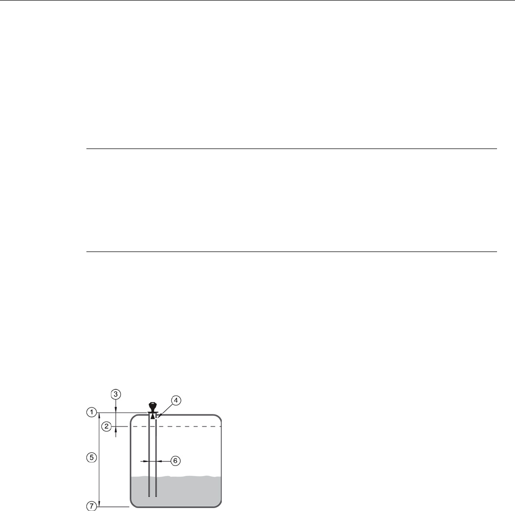
This application is to obtain a level measurement and corresponding 4 to 20 mA output
proportional to the oil level in a fuel storage vessel.
● Low Calibration Pt. is 5 m (16.4 ft) from the sensor reference point.
● High Calibration Pt. is 0.5 m (1.64 ft) from the sensor reference point.
● The stillpipe inside diameter is 50 mm (1.96").
● The maximum rate of filling or emptying is about 0.1 m (4")/min.
①
Sensor reference point
⑤
5 m
②
High calibration point
⑥
50 mm I.D.
③
0.5
m
⑦
Low calibration point
④
Vent hole