
User's Manual
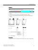
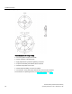
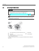
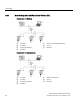
Table Of Contents
- SITRANS LR250 (FOUNDATION FIELDBUS)
- Legal information
- Table of contents
- 1 Introduction
- 2 Safety notes
- 3 Description
- 4 Installing/mounting
- 5 Connecting
- 6 Commissioning
- 7 Remote operation
- 7.1 Operating via AMS Device Manager
- 7.1.1 Functions in AMS Device Manager
- 7.1.2 Key features of AMS Device Manager Rev. 9.0
- 7.1.3 Adding a new device
- 7.1.4 Master Reset
- 7.1.5 Scan Device
- 7.1.6 Sensor calibration
- 7.1.7 Configuring a new device
- 7.1.8 Changing parameter settings using AMS Device Manager
- 7.1.9 Configure/Setup (Level Transducer Block-LTB)
- 7.1.10 Configure/Setup (Liquid Crystal Display Block-LCD)
- 7.1.11 Configure/Setup (Diagnostic Transducer Block-DIAG)
- 7.1.12 Configure/Setup (Resource Block - RESOURCE)
- 7.1.13 Device Diagnostics (Level Transducer Block - LTB)
- 7.1.14 Device Diagnostics (Liquid Crystal Display Block - LCD)
- 7.1.15 Device Diagnostics (Diagnostic Transducer Block - DIAG)
- 7.1.16 Device Diagnostics (Resource Block - RESOURCE)
- 7.1.17 Process Variables (Level Transducer Block - LTB)
- 7.1.18 Password Protection
- 7.1.19 AMS menu structure
- 7.1 Operating via AMS Device Manager
- 8 Parameter reference
- 9 Service and maintenance
- 10 Diagnosing and troubleshooting
- 11 Technical data
- 12 Dimension drawings
- 12.1 Threaded horn antenna
- 12.2 Threaded horn antenna with extension
- 12.3 Flanged horn antenna
- 12.4 Flanged horn antenna with extension
- 12.5 Flanged encapsulated antenna (2"/DN50/50A sizes only)
- 12.6 Flanged encapsulated antenna (3"/DN80/80A sizes and larger)
- 12.7 Threaded PVDF antenna
- 12.8 Threaded connection markings
- 12.9 Raised-Face flange per EN 1092-1 for flanged horn antenna
- 12.10 Raised-Face flange per EN 1092-1 for flanged encapsulated antenna
- 12.11 Flat-Face flange
- 12.12 Process connection tag (pressure rated versions)
- A Appendix A: Technical reference
- B Appendix B: Communications via Foundation Fieldbus
- C Appendix C: Certificates and support
- 13 List of abbreviations
- 14 LCD menu structure
- Glossary
- Index

Connecting
5.2 Connecting SITRANS LR250
SITRANS LR250 (FOUNDATION FIELDBUS)
Operating Instructions, 01/2014, A5E32221411-AB
27
Wiring instructions
1. Strip the cable jacket for approximately 70 mm (2.75") from the end of the cable, and thread
the wires through the gland. (If cable is routed through conduit, use only approved suitable-
size hubs for waterproof applications.)
2. Connect the wires to the terminals as shown: the polarity is identified on the terminal block.
3. Ground the device according to local regulations.
4. Tighten the gland to form a good seal.
5. Close the lid and secure the locking screw before programming and device configuration.
Note
•
Foundation Fieldbus (H1) must be terminated at both extreme ends of the cable for it to
work properly.
•
For optimum EMC protection, it is recommended that the FF H1 cable shield be
connected to ground at every node.
•
Please refer to the Foundation Fieldbus System Engineering Guidelines (AG-181)
Revision 2.0, for information on installing FF (H1) devices available from:
Foundation Fieldbus (
http://www.fieldbus.org/)
•
If a Weidmüller or other current limiting junction box is connected to this device, please
ensure that the current limit is set to 40 mA or higher.