
User's Manual
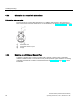
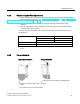
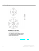
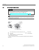
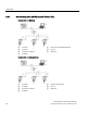
Table Of Contents
- SITRANS LR250 (FOUNDATION FIELDBUS)
- Legal information
- Table of contents
- 1 Introduction
- 2 Safety notes
- 3 Description
- 4 Installing/mounting
- 5 Connecting
- 6 Commissioning
- 7 Remote operation
- 7.1 Operating via AMS Device Manager
- 7.1.1 Functions in AMS Device Manager
- 7.1.2 Key features of AMS Device Manager Rev. 9.0
- 7.1.3 Adding a new device
- 7.1.4 Master Reset
- 7.1.5 Scan Device
- 7.1.6 Sensor calibration
- 7.1.7 Configuring a new device
- 7.1.8 Changing parameter settings using AMS Device Manager
- 7.1.9 Configure/Setup (Level Transducer Block-LTB)
- 7.1.10 Configure/Setup (Liquid Crystal Display Block-LCD)
- 7.1.11 Configure/Setup (Diagnostic Transducer Block-DIAG)
- 7.1.12 Configure/Setup (Resource Block - RESOURCE)
- 7.1.13 Device Diagnostics (Level Transducer Block - LTB)
- 7.1.14 Device Diagnostics (Liquid Crystal Display Block - LCD)
- 7.1.15 Device Diagnostics (Diagnostic Transducer Block - DIAG)
- 7.1.16 Device Diagnostics (Resource Block - RESOURCE)
- 7.1.17 Process Variables (Level Transducer Block - LTB)
- 7.1.18 Password Protection
- 7.1.19 AMS menu structure
- 7.1 Operating via AMS Device Manager
- 8 Parameter reference
- 9 Service and maintenance
- 10 Diagnosing and troubleshooting
- 11 Technical data
- 12 Dimension drawings
- 12.1 Threaded horn antenna
- 12.2 Threaded horn antenna with extension
- 12.3 Flanged horn antenna
- 12.4 Flanged horn antenna with extension
- 12.5 Flanged encapsulated antenna (2"/DN50/50A sizes only)
- 12.6 Flanged encapsulated antenna (3"/DN80/80A sizes and larger)
- 12.7 Threaded PVDF antenna
- 12.8 Threaded connection markings
- 12.9 Raised-Face flange per EN 1092-1 for flanged horn antenna
- 12.10 Raised-Face flange per EN 1092-1 for flanged encapsulated antenna
- 12.11 Flat-Face flange
- 12.12 Process connection tag (pressure rated versions)
- A Appendix A: Technical reference
- B Appendix B: Communications via Foundation Fieldbus
- C Appendix C: Certificates and support
- 13 List of abbreviations
- 14 LCD menu structure
- Glossary
- Index

Installing/mounting
4.3 Installation instructions
SITRANS LR250 (FOUNDATION FIELDBUS)
22 Operating Instructions, 01/2014, A5E32221411-AB
4.3
Installation instructions
WARNING
For pressure applications, it will be necessary to use PTFE tape or other appropriate thread
sealing compound, and to tighten the process connection beyond hand-tight. (The
maximum recommended torque for Threaded versions is 40 N-m (30 ft.lbs.) See Flange
bolting, Flanged encapsulated antenna only (Page 23) for FEA recommended torque
values.)
Note
•
On devices with a removable head, there is no limit to the number of times a device can
be rotated without damage.
•
When mounting, orient the front or back of the device towards the closest wall.
•
Do not rotate the enclosure after programming and vessel calibration, otherwise an error
may occur, caused by a polarity shift of the transmit pulse.
Threaded versions
1. Before inserting the device into its mounting connection, check to ensure the threads are
matching, to avoid damaging them.
2. Simply screw the device into the process connection, and hand tighten, or use a wrench.
For pressure applications see Warning above.
Flanged versions
See Flanged Horn with extension (Page 210), Raised-Face Flange per EN 1092-1 (Page 222),
Flat-Face Flange (Page 225), and Flanged encapsulated antenna (3"/DN80/80A sizes and
larger) (Page 216) for dimensions.