
User's Manual
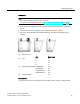
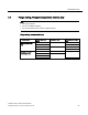
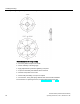
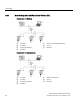
Table Of Contents
- SITRANS LR250 (FOUNDATION FIELDBUS)
- Legal information
- Table of contents
- 1 Introduction
- 2 Safety notes
- 3 Description
- 4 Installing/mounting
- 5 Connecting
- 6 Commissioning
- 7 Remote operation
- 7.1 Operating via AMS Device Manager
- 7.1.1 Functions in AMS Device Manager
- 7.1.2 Key features of AMS Device Manager Rev. 9.0
- 7.1.3 Adding a new device
- 7.1.4 Master Reset
- 7.1.5 Scan Device
- 7.1.6 Sensor calibration
- 7.1.7 Configuring a new device
- 7.1.8 Changing parameter settings using AMS Device Manager
- 7.1.9 Configure/Setup (Level Transducer Block-LTB)
- 7.1.10 Configure/Setup (Liquid Crystal Display Block-LCD)
- 7.1.11 Configure/Setup (Diagnostic Transducer Block-DIAG)
- 7.1.12 Configure/Setup (Resource Block - RESOURCE)
- 7.1.13 Device Diagnostics (Level Transducer Block - LTB)
- 7.1.14 Device Diagnostics (Liquid Crystal Display Block - LCD)
- 7.1.15 Device Diagnostics (Diagnostic Transducer Block - DIAG)
- 7.1.16 Device Diagnostics (Resource Block - RESOURCE)
- 7.1.17 Process Variables (Level Transducer Block - LTB)
- 7.1.18 Password Protection
- 7.1.19 AMS menu structure
- 7.1 Operating via AMS Device Manager
- 8 Parameter reference
- 9 Service and maintenance
- 10 Diagnosing and troubleshooting
- 11 Technical data
- 12 Dimension drawings
- 12.1 Threaded horn antenna
- 12.2 Threaded horn antenna with extension
- 12.3 Flanged horn antenna
- 12.4 Flanged horn antenna with extension
- 12.5 Flanged encapsulated antenna (2"/DN50/50A sizes only)
- 12.6 Flanged encapsulated antenna (3"/DN80/80A sizes and larger)
- 12.7 Threaded PVDF antenna
- 12.8 Threaded connection markings
- 12.9 Raised-Face flange per EN 1092-1 for flanged horn antenna
- 12.10 Raised-Face flange per EN 1092-1 for flanged encapsulated antenna
- 12.11 Flat-Face flange
- 12.12 Process connection tag (pressure rated versions)
- A Appendix A: Technical reference
- B Appendix B: Communications via Foundation Fieldbus
- C Appendix C: Certificates and support
- 13 List of abbreviations
- 14 LCD menu structure
- Glossary
- Index
Installing/mounting
4.2 Mounting location
SITRANS LR250 (FOUNDATION FIELDBUS)
Operating Instructions, 01/2014, A5E32221411-AB
21
4.2.5
Stillpipe or Bypass Pipe requirements
● The pipe diameter must be matched with the antenna size. Use the largest antenna size that
will fit the stillpipe/bypass pipe
1)
. See Threaded Horn dimensions (Page 205) or Raised-Face
Flange per EN 1092-1 (Page 222).
● One continuous length of metallic pipe is preferred, without joints. Bad joints create
reflections.
● Joints (if unavoidable) must be machined to ± 0.25 mm (± 0.010") and must have welded
connecting sleeve on the outside.
1)
Mounting in a pipe greater than 100 mm (4") can cause large errors, and therefore is not
recommended.
Suitable pipe diameters:
Horn antenna
40 to 100 mm (1.5 to 4")
PVDF antenna
50 mm (2") only
Flanged encapsulated antenna
50 to 100 mm (2 to 4")
Not recommended:
> 100 mm (4")
Bypass vent:
Required at the upper end of the bypass
1)
1)
To equalize pressure and keep the liquid level in the bypass constant with the liquid level in the
vessel.
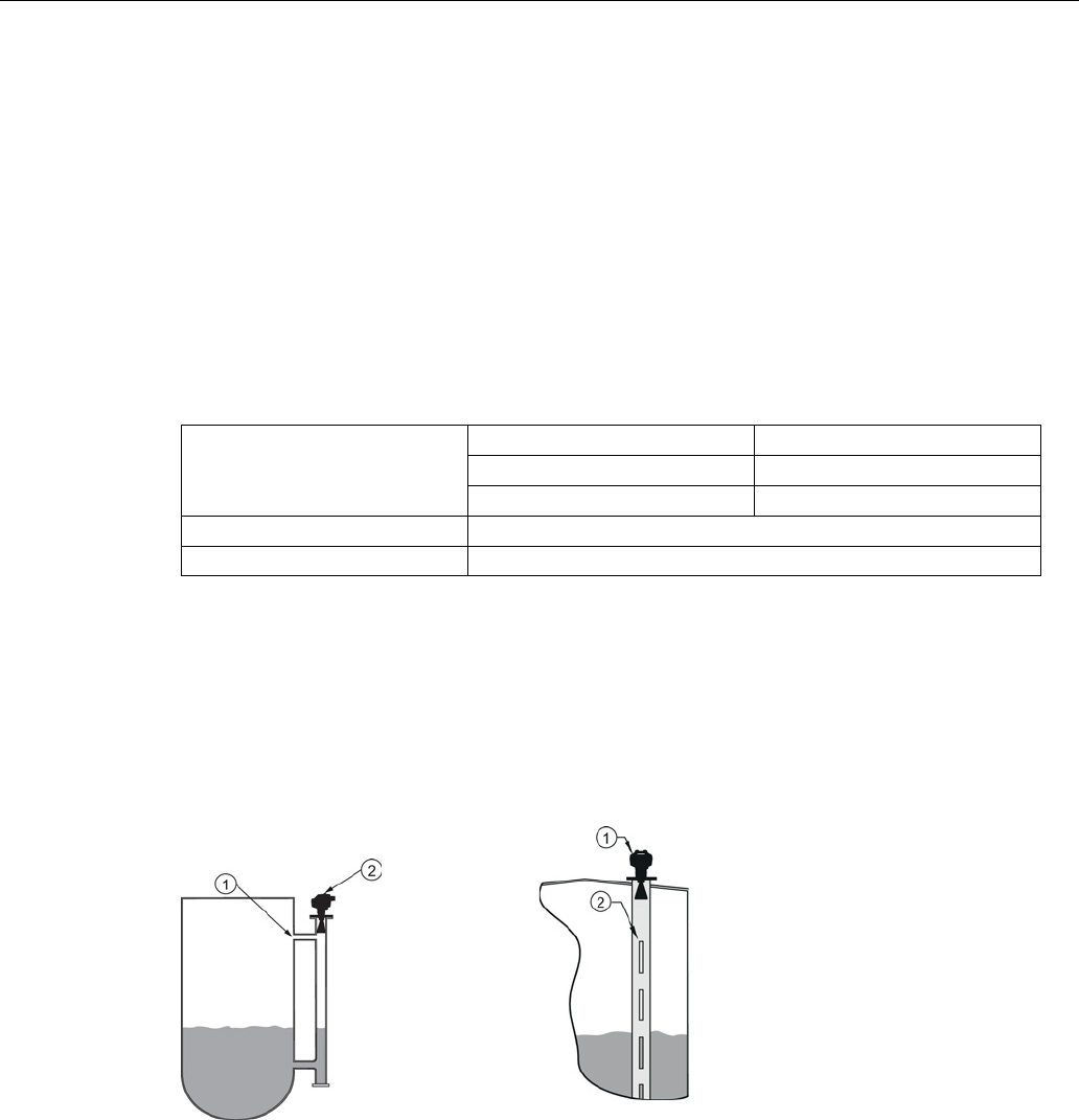
4.2.6
Device orientation
Bypass pipe installation
Stillpipe installation
①
Vent
①
Align front or back of device with stillpipe slots
1)
②
Align front or back of device with
vents
1)
②
Slots
1)
Horn antenna version shown as example