
User's Manual
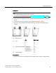
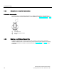
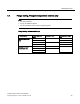
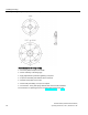
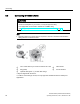
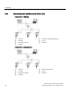
Table Of Contents
- SITRANS LR250 (FOUNDATION FIELDBUS)
- Legal information
- Table of contents
- 1 Introduction
- 2 Safety notes
- 3 Description
- 4 Installing/mounting
- 5 Connecting
- 6 Commissioning
- 7 Remote operation
- 7.1 Operating via AMS Device Manager
- 7.1.1 Functions in AMS Device Manager
- 7.1.2 Key features of AMS Device Manager Rev. 9.0
- 7.1.3 Adding a new device
- 7.1.4 Master Reset
- 7.1.5 Scan Device
- 7.1.6 Sensor calibration
- 7.1.7 Configuring a new device
- 7.1.8 Changing parameter settings using AMS Device Manager
- 7.1.9 Configure/Setup (Level Transducer Block-LTB)
- 7.1.10 Configure/Setup (Liquid Crystal Display Block-LCD)
- 7.1.11 Configure/Setup (Diagnostic Transducer Block-DIAG)
- 7.1.12 Configure/Setup (Resource Block - RESOURCE)
- 7.1.13 Device Diagnostics (Level Transducer Block - LTB)
- 7.1.14 Device Diagnostics (Liquid Crystal Display Block - LCD)
- 7.1.15 Device Diagnostics (Diagnostic Transducer Block - DIAG)
- 7.1.16 Device Diagnostics (Resource Block - RESOURCE)
- 7.1.17 Process Variables (Level Transducer Block - LTB)
- 7.1.18 Password Protection
- 7.1.19 AMS menu structure
- 7.1 Operating via AMS Device Manager
- 8 Parameter reference
- 9 Service and maintenance
- 10 Diagnosing and troubleshooting
- 11 Technical data
- 12 Dimension drawings
- 12.1 Threaded horn antenna
- 12.2 Threaded horn antenna with extension
- 12.3 Flanged horn antenna
- 12.4 Flanged horn antenna with extension
- 12.5 Flanged encapsulated antenna (2"/DN50/50A sizes only)
- 12.6 Flanged encapsulated antenna (3"/DN80/80A sizes and larger)
- 12.7 Threaded PVDF antenna
- 12.8 Threaded connection markings
- 12.9 Raised-Face flange per EN 1092-1 for flanged horn antenna
- 12.10 Raised-Face flange per EN 1092-1 for flanged encapsulated antenna
- 12.11 Flat-Face flange
- 12.12 Process connection tag (pressure rated versions)
- A Appendix A: Technical reference
- B Appendix B: Communications via Foundation Fieldbus
- C Appendix C: Certificates and support
- 13 List of abbreviations
- 14 LCD menu structure
- Glossary
- Index

Installing/mounting
4.2 Mounting location
SITRANS LR250 (FOUNDATION FIELDBUS)
20 Operating Instructions, 01/2014, A5E32221411-AB
4.2.3
Orientation in a vessel with obstructions
Polarization reference point
For best results on a vessel with obstructions, or a stillpipe with openings, orient the front or
back of the device toward the obstructions. For an illustration, see Device orientation (Page 21).
①
Polarization axis
②
Polarization reference point
③
Display
4.2.4
Mounting on a Stillpipe or Bypass Pipe
A stillpipe or bypass pipe is used for products with a low dK, or when vortex or extremely
turbulent conditions exist. It can also be used to provide optimum signal conditions on foaming
materials. See Dielectric constant of material measured in Performance (Page 198) for more
information.