
User's Manual
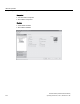
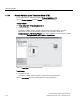
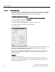
Table Of Contents
- SITRANS LR250 (FOUNDATION FIELDBUS)
- Legal information
- Table of contents
- 1 Introduction
- 2 Safety notes
- 3 Description
- 4 Installing/mounting
- 5 Connecting
- 6 Commissioning
- 7 Remote operation
- 7.1 Operating via AMS Device Manager
- 7.1.1 Functions in AMS Device Manager
- 7.1.2 Key features of AMS Device Manager Rev. 9.0
- 7.1.3 Adding a new device
- 7.1.4 Master Reset
- 7.1.5 Scan Device
- 7.1.6 Sensor calibration
- 7.1.7 Configuring a new device
- 7.1.8 Changing parameter settings using AMS Device Manager
- 7.1.9 Configure/Setup (Level Transducer Block-LTB)
- 7.1.10 Configure/Setup (Liquid Crystal Display Block-LCD)
- 7.1.11 Configure/Setup (Diagnostic Transducer Block-DIAG)
- 7.1.12 Configure/Setup (Resource Block - RESOURCE)
- 7.1.13 Device Diagnostics (Level Transducer Block - LTB)
- 7.1.14 Device Diagnostics (Liquid Crystal Display Block - LCD)
- 7.1.15 Device Diagnostics (Diagnostic Transducer Block - DIAG)
- 7.1.16 Device Diagnostics (Resource Block - RESOURCE)
- 7.1.17 Process Variables (Level Transducer Block - LTB)
- 7.1.18 Password Protection
- 7.1.19 AMS menu structure
- 7.1 Operating via AMS Device Manager
- 8 Parameter reference
- 9 Service and maintenance
- 10 Diagnosing and troubleshooting
- 11 Technical data
- 12 Dimension drawings
- 12.1 Threaded horn antenna
- 12.2 Threaded horn antenna with extension
- 12.3 Flanged horn antenna
- 12.4 Flanged horn antenna with extension
- 12.5 Flanged encapsulated antenna (2"/DN50/50A sizes only)
- 12.6 Flanged encapsulated antenna (3"/DN80/80A sizes and larger)
- 12.7 Threaded PVDF antenna
- 12.8 Threaded connection markings
- 12.9 Raised-Face flange per EN 1092-1 for flanged horn antenna
- 12.10 Raised-Face flange per EN 1092-1 for flanged encapsulated antenna
- 12.11 Flat-Face flange
- 12.12 Process connection tag (pressure rated versions)
- A Appendix A: Technical reference
- B Appendix B: Communications via Foundation Fieldbus
- C Appendix C: Certificates and support
- 13 List of abbreviations
- 14 LCD menu structure
- Glossary
- Index
Remote operation
7.1 Operating via AMS Device Manager
SITRANS LR250 (FOUNDATION FIELDBUS)
114 Operating Instructions, 01/2014, A5E32221411-AB
7.1.17
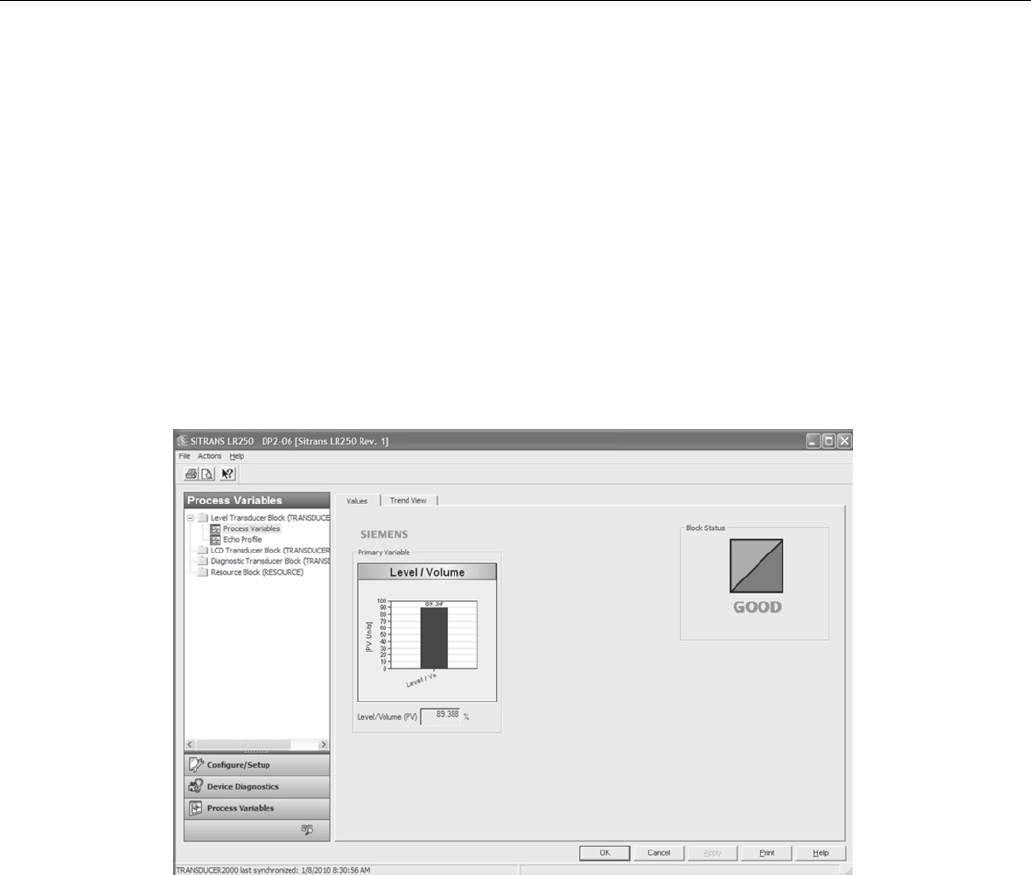
Process Variables (Level Transducer Block - LTB)
To compare outputs in real time navigate to
Process Variables > LTB
.
Click on
Process Variables
then the
Values
tab to read the following:
Primary Variable
[see
Main Output (PV - Primary Value) (2.8.1.)
]
● Level/Volume (PV)
The primary variable and the channel 1 output from the transducer block. For level
applications, chart range is affected by High and Low Level Point values set in
Configure/Setup > LTB > Setup > Sensor
. For volume applications, chart range is 0 to Max.
Volume, set in
Configure/Setup > LTB > Setup > Linearization
.
Click on
Trend View
tab to read the following:
Trend Values
● Level/Volume (PV)
The primary variable and the channel 1 output from the transducer block.
Click on
Echo Profile
to open the dialog window to read the following: