
Technical information
IM-P343-29 CH Issue 5 49
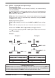
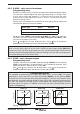
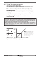
Fig. 44 TS1 Travel switch 1 (normally open)
Switch
closed
Signal
Switch
open
Travel
100%
0%
Note:
Software configured travel
switches can be set within
the range 0% to 100% of
full travel irrespective of any
travel limit settings.
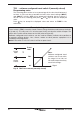
9.6.7 TS1 and TS2 software travel switches
Two switches are available TS1 and TS2.
TS1 is normally open and TS2 is normally closed. Switching action is set as
a % of valve travel (refer to Figures 44 and 45).
TS1 - software configured travel switch 1 (normally open)
Programming notes
The switching point can be set as a percentage of the valve travel between 0
to100%. A value can be set outside the limits of the travel settings (MIN-T)
and (MAX-T).
Initially OFF will be displayed indicating that the switch is not set. To set a
switching point press and keys to alter the displayed value.
Press
key to accept the displayed value and advance to travel switch 2
normally closed (TS2).
Commissioning notes
Travel switch 1 (TS1) is normally open. External wiring should be made between terminals
1 (
+) and 2 (-). The value set is a % of valve travel. At the set value the switch will close.
The status of the switch will be shown on the LCD (refer to Figure 44).
Software configured travel switches can be used to remotely indicate valve position or
to operate warning devices, fans, stirrers, motors or other process equipment via a
secondary switching device.
50%