
Technical information
IM-P343-29 CH Issue 5 21
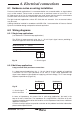
6. Electrical connections
6.1 Guidance notes on wiring installation
For heavy industrial applications it is recommended to use screened cables or signal cables
run in metal conduit. Failure to do so could result in positional errors of up to ±5% in an
RF field excess of 10 V/m. If screened cables are used, ensure that the screen is connected to
the local earth at one end with a connection resistance of less than 1 ohm.
For light industrial applications where RF fields do not exceed 3 V/m unscreened cables
may be used.
Cabling should be installed in accordance with BS 6739 - Instrumentation in Process Control
Systems: Installation design and practice or local equivalent.
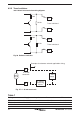
6.2 Wiring diagrams
6.2.1 Single loop applications
(see Section 6.2.2 for Multi-loop applications)
The SP200 is loop powered using the 4 - 20 mA input signal source providing a
minimum signal of 3.6 mA can be maintained.
Minimum current = 3.6 mA
Maximum current = 30 mA
Voltage drop = 10.6 V @ 20 mA
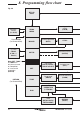
6.2.2 Multi-loop applications
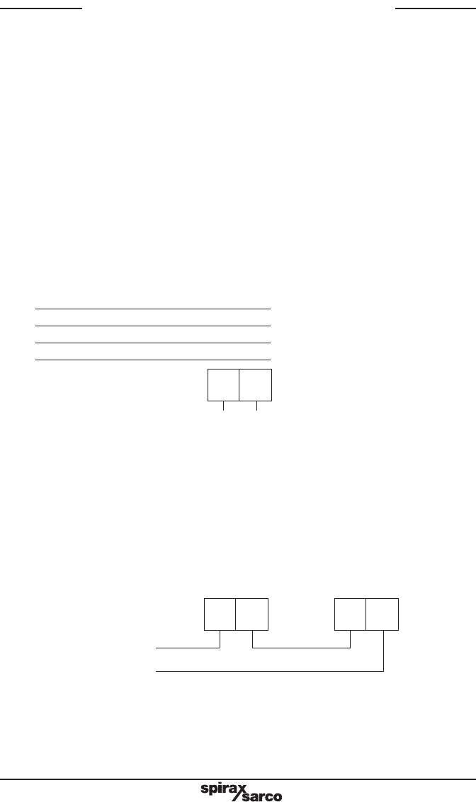
Loop powered multi-positioner connections
In a loop powered application, the 4 - 20 mA signal must be capable of supplying
a minimum of 10.6 V per positioner at 20 mA. In a split range application the
signal source loop must be capable of supplying sufficient voltage, i.e. 22 V are enough
to power 2 positioners (Figure 16).
4 - 20 mA signal
+
@ 22 V minimum
-
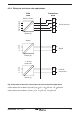
In terms of impedance, this means that in split range application, the load in the
loop at 20 mA is 1060 Ohm. The impedance of a single SP200 is 530 Ohm at 20 mA.
A typical controller might not be able to drive such a impedance load, hence a different
approach is required.
A 4-20 mA current splitter can provide a solution to this problem for further information
please contact Spirax Sarco.
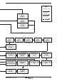
Fig. 24
4 - 20 mA signal
5 6
+ -
5 6
Positioner 1
5 6
Positioner 2
Fig. 25