
Technical information

IM-P343-29 CH Issue 5 19
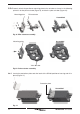
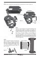
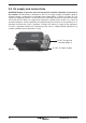
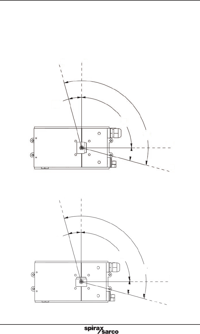
5.3.2 Adjust the magnet orientation as illustrated in Figures 21 and 22 and tighten the bolt to
fix the magnet into position. There should be a distance of between 5 and 14 mm between
the magnet and the positioner.
Refer to Figure 21 for actuator with clockwise rotation.
Refer to Figure 22 for actuator with anti-clockwise rotation.
In fact, in this way the magnet movements will always be comprised in the sector between
the directions C and D which delimit the operating area of the Hall sensor.
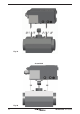
Fig. 21 View from the bottom of the positioner - Magnet orientation for clockwise
actuator.
Fig. 22 View from bottom of the positioner - Magnet orientation for anti-clockwise
actuator.
D
B
A
C
15°
90°
120°
15°
D
B
A
C
15°
90°
120°
15°