
Technical information

IM-P343-29 CH Issue 5 15
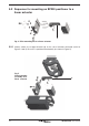
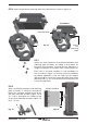
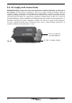
5.2.6 Attach the positioner mounting plate to the positioner as shown in Figure 12.
Protection plate
Attach
the
mounting
plate
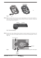
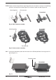
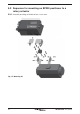
5.2.8
When the SP200 positioner and mounting
plate assembly is correctly positioned,
tighten the hexagon headed screw (
5) on
the yoke mounted actuator (Figure 12) to
10 - 12 N m and tighten the 'U'bolt nuts (
6)
on the pillar mounted actuators (Figure 14)
to 10 - 12 N m.
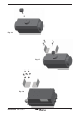
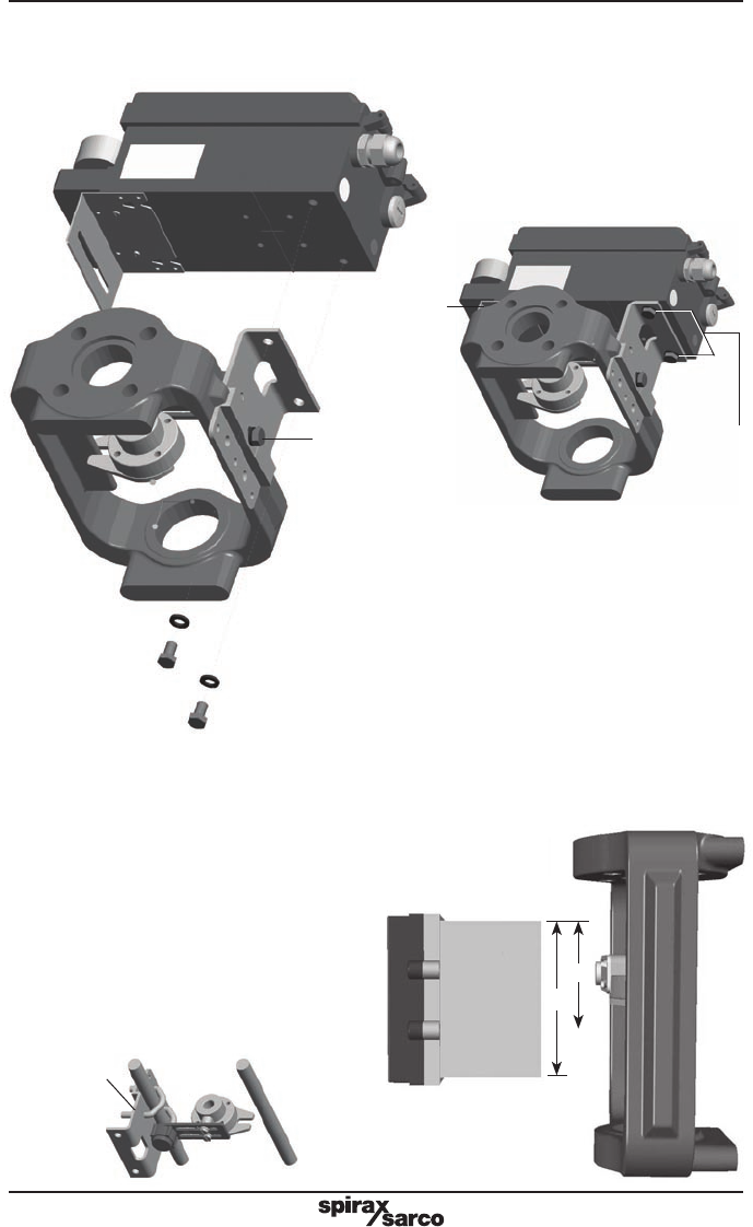
5.2.7
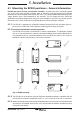
Adjust the vertical position of the SP200 positioner and
mounting plate assembly, by sliding it up or down on
the pillar style actuators, ensuring that the positioner is
roughly centred on the actuator / valve stroke (Figure 10).
Even if this is the ideal condition, it’s not mandatory. In
fact, as shown in Figure 13, the only necessary condition
for correct operation is that the stroke of the magnet
(dimension
B) lay inside the sensor operating linear range
(dimension A), i.e. the vertical dimension marked on the
case of the positioner.
6
5
Fig. 14
Fig. 12
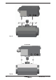
B
A
Fig. 13
Assembled
SP200 positoner