3439650/5 IM-P343-29 CH Issue 5 SP200 Electropneumatic Smart Positioner Installation and Maintenance Instructions 1. 2. 3. 4. 5. 6. 7. 8. 9. 10. 11. 12. 13.
IM-P343-29 CH Issue 5
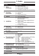
1. Index Section Sub-section 2.1 2.2 General requirements Electrical safety requirements 2.3 2.4 Electromagnetic compatibility Installation for hazardous areas and certification 3. Technical information 3.1 3.2 3.3 3.4 Description Technical data Materials Programmable functions 4. Options 4.1 Pressure gauge block 5.1 Mounting the SP200 positioner General informaton Sequence for mounting an SP200 positioner to a linear actuator Sequence for mounting an SP200 positioner to a rotary actuator 2.
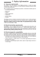
2. Safety information 2.1 General requirements The flawless and safe operation of the SP200 positioners is reliant on proper transportation, storage, installation and commissioning by qualified personnel, proper use and careful maintenance. Prior to installing, using or maintaining the positioner, consideration should be given to: - The working environment. Safe access. Lighting. Pipeline fluid hazards. Temperature. System isolation. Location.
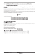
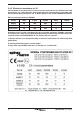
2.4 Installation for hazardous areas and certification - General information SP200 Smart Positioner is available for Intrinsic Safety applications, model identification is SP200is. In case of use in hazardous areas with danger of explosion, it must be verified that the identified type of positioner fits for the classification of the zone and for the presence of flammable substances in the plant. Model SP200is is certified by EC-type Examination Certificate N.
2.4.2 Electrical connections for IS. For installation in classified areas it is necessary to foresee the use of certified associated apparatuses (e.g. safety barriers), with output electrical characteristics compatible with the maximum input parameters (ref.
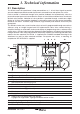
3. Technical information 3.1 Description The SP200 smart valve positioner is loop powered from a 4 - 20 mA input signal to provide accurate adaptive positional control of pneumatic actuated linear and quarter turn valves. Precise control is maintained through valve position feedback that automatically varies the pneumatic output pressure to overcome the effects of stem friction and flow forces to maintain desired valve position.
3.2 Technical data Input signal range 4 - 20 mA nominal Minimum input signal (loop powered) 3.6 mA Minimum air supply pressure 1.0 bar g above maximum spring range pressure (Note: For the PN5120 actuator, the supply air pressure should be set at 1.5 bar g) Maximum air supply pressure 6.
3.
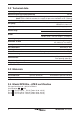
4. Options 4.1 Pressure gauge block An optional pressure gauge block (Figure 2) can be fitted onto the SP200 positioner which includes two pressure gauges indicating air supply pressure and output air signal pressure to the actuator. For double action valves the gauge block includes 3 pressure gauges indicating: air supply pressure, output 1 air signal and output 2 air signal. The pressure gauge block can be retrospectively fitted using 2 off M5 Allen screws.
5. Installation 5.1 Mounting the SP200 positioner - General information Preliminary check of valve and actuator assembly - A preliminary check should be carried out on the valve and actuator assembly prior to mounting and commissioning the SP200 positioner to confirm smooth movement of the stem. This can be performed by providing an air supply directly from a filter / regulator to the actuator. The air supply pressure should be gradually increased to progressively move the stem through its full travel.
5.2 Sequence for mounting an SP200 positioner to a linear actuator 2 Fig. 4 Pillar mounting kit for a linear actuator 5.2.1 Loosely attach the magnet bracket (2) to the valve / actuator connector (refer to Figures 4 and 5). Be sure it is positioned horizontally (as shown in Figure 5). Fig.
Assembled 2 Fig. 6 5.2.2 Slide the bracket (2) to the left or to the right (Figure 6) till the correct position is achieved. If you’re using a Spirax Sarco actuator the correct position is impressed on the magnet bracket (Figure 7). PN9000 PN1000 Fig. 7 Bracket markings 5.2.3 If you’re not using a Spirax Sarco actuator, slide the bracket till the distance 'A' between the center of the magnet and the inner side of the mounting plate is 25 mm (Figure 8). Mounting plate Bracket Fig.
5.2.4 Loosely attach the positioner mounting plate to the actuator as shown in the following pictures: for the pillar actuator (Figure 9), and for the yoke actuator (Figure 10). Mounting plate Pillar actuator Assembled Fig. 9 Pillar actuator assembly Mounting plate Assembled Yoke actuator Fig.10 Yoke actuator assembly 5.2.5 Locate the protection plate onto the back of the SP200 positioner housing and fix in place (Figure 11). Protection plate Assembled Fig.
5.2.6 Attach the positioner mounting plate to the positioner as shown in Figure 12. Assembled Protection plate 5 Attach the mounting plate Fig. 12 5.2.7 Adjust the vertical position of the SP200 positioner and mounting plate assembly, by sliding it up or down on the pillar style actuators, ensuring that the positioner is roughly centred on the actuator / valve stroke (Figure 10). Even if this is the ideal condition, it’s not mandatory.
5.3 Sequence for mounting an SP200 positioner to a rotary actuator 5.3.1 Assembly for fitting an SP200 on to a ¼ turn valve. Fig.
Fig. 16 Fig. 17 Fig.
Fig. 19 Assembled Fig.
5.3.2 Adjust the magnet orientation as illustrated in Figures 21 and 22 and tighten the bolt to fix the magnet into position. There should be a distance of between 5 and 14 mm between the magnet and the positioner. Refer to Figure 21 for actuator with clockwise rotation. Refer to Figure 22 for actuator with anti-clockwise rotation. In fact, in this way the magnet movements will always be comprised in the sector between the directions C and D which delimit the operating area of the Hall sensor.
5.4 Air supply and connections WARNING: Supply air pressure must not exceed the maximum allowable air pressure of the actuator. Air connections should be ¼" NPT for air supply (supply) and output signal to actuator (output 1 and output 2 for double action applications) as shown in Figure 23. The supply air should be between 1.4 bar g minimum and 6 bar g maximum and be oil and dust free to IEC 60770.
6. Electrical connections 6.1 Guidance notes on wiring installation For heavy industrial applications it is recommended to use screened cables or signal cables run in metal conduit. Failure to do so could result in positional errors of up to ±5% in an RF field excess of 10 V/m. If screened cables are used, ensure that the screen is connected to the local earth at one end with a connection resistance of less than 1 ohm.
6.2.3 Travel switches- and 4-20 mA retransmission wiring digrams 2 k 1 22 k Travel switches 1 2 2 k 3 22 k Travel switches 2 4 Fig. 26 Software switches Example of customers external application wiring. ������� 4 - 20 mA retransmit �������� ������ ��������� ��������� ������ ������ - Fig. 27 4 - 20 mA retransmit Table 1 Ratings TS1 travel switch TS2 travel switch 4 - 20 mA 22 Supply 18 - 30 Vdc 18 - 30 Vdc 8 - 30 Vdc Impedance 1.8 k 1.
6.2.4 Wiring for instrinsic safe applications Safe area Hazardous area Switch 1 and 2 Digital outputs 1 2 3 Travel switches 4 Barrier (a) 4 - 20 mA Supply 5 6 Signal Barrier (b) 4 - 20 mA 4 - 20 mA retransmit 7 8 Position transmitter Barrier (c) Fig.
7. Quick start procedure 7.1 2-port valves The following applies to positioners fitted to 2-port valves having plug above the seat and fitted to pneumatic actuators having a direct acting (DIR) 4 - 20 mA input signal and excludes the setting of any additional program functions (i.e. default value only). Note: For PN5100 and PN6100 series actuators an additional programming step is required. (Refer to Section 9.5.2). 7.1.
7.2 3-port valves (with travel setting (TRAVL) 0 - 100%, refer to Figures 27 and 28) Proceed as above up to Section 7.1.9. 7.2.1 On completion of a successful autostroke press the key once to advance to SET in main menu. 7.2.2 Press Press key once to advance to VALVE TYPE. key to indicate VALVE 3-PORT. 7.2.3 Press key to select VALVE 3-PORT. Continue to press main menu. key to return to SET in 7.2.4 Press key twice to advance to RUN in main menu. Proceed as described in Section 7.1.11.
8. Programming flow chart Fig. 29 SET-UP NOW Software version (Ver X.
Key 3 seconds enter Enter Clear stored values (RESET) Auto return Recall stored values (RETRN) Retain temporary values (RTAIN) Minimum travel (MIN-T) Maximum travel (MAX-T) Displayed % travel (DTRVL)† Minimum range (MIN-R) Maximum range (MAX-R) † Only if MIN-T / MAX-T not 0 / 100% Control action (CTRLA) Shut-off maximum (S-MAX) Characterisation (LIN / FAST / EQUAL) Time to open (T-UP) Time to close (T-dWN) AUTO OPERATION (mA Input signal) Stem travel (STRVL) Travel switch 2 (NC) (TS2) Trave
9. Programming and commissioning 9.1 Set-up now Programming notes The positioner fitted to this control valve requires programming. A minimum input signal of 3.6 mA is required to power the positioner. To program the positioner it is necessary to enter SP200 MENU and carry out an autostroke commissioning routine (AUTOS) prior to putting the control valve into automatic operation. A flow chart is included in Section 8 to guide you through the procedure.
9.2 SP200 MENU � SET-UP NOW 3 seconds enter Clear stored values (RESET) 3 seconds enter Software version (Ver X.XX) SP200 MENU Mounting position check (CALIB) Recall stored values (RETRN) Retain temporary values (RTAIN) From RETRN Fig. 30 Programming notes You are now in SP200 MENU. SP200 functions include: 1. Visualisation of the embedded software version (VER--). 2. Positional setting (CALIB). 3. Resetting of programmed values to default settings (RESET). 4.
9.2.2 CALIB - mounting position calibration Programming notes To access CALIB press and hold key for 3 seconds. The display will count down the 3 seconds. You are now in calibrate mode. The LCD shows in % the magnet position in respect to the sensor board of the positioner, without any offset or scale up or down. When the LCD shows 0% the magnet is positioned near the bottom of the positioner’s case. At 50% the magnet will be in front of the cross impressed on the back of the positioner.
9.2.3 RETRN - RTAIN - RESET Programming notes Provides the facility to restore previous permanently stored values (RETRN), to retain values stored in the temporary memory (RTAIN) or to reset all values and keys to select RETRN, to factory default settings (RESET). Press RTAIN or RESET. To advance proceed as follows: RETRN To cancel any temporary changes to programmed values select RETRN and press key to return to SP200 MENU.
9.3 MANOP 3 second enter MANOP Manual operation (MCTL) C-CAL Fig. 31 Programming notes Press and hold key for 3 seconds to enter manual control mode (MCTL). The display will count down the 3 seconds. Press the key to enter the current calibration mode (C-CAL). Press return to MANOP. In MANOP press to key to advance to autostroke (AUTOS).
9.3.2 C-CAL - current calibration Programming notes C-Cal provides a simple way to make a fine calibration of the input current signal (4 - 20 mA). To perform the calibration: 1. Enter C-CAL and press the key, then press the 2. Generate a 4 mA input signal and press 3. Generate a 12 mA input signal and press 4. Generate a 20 mA input signal and press key. If 'ERROR' is displayed the calibration routine is aborted. The value of the generated signal is too far from the expected one.
9.4 AUTOS - automatic autostroke commissioning % Travel (TRAVL 0-100% / 100-0%) AUTOS 3 second Autostroke activate enter (AUTOS) Fig. 32 Programming notes AUTOS provides access to: 1. Autostroke commissioning (AUTOS). 2. % travel display (TRAVL). AUTOS Autostroke provides an automatic commissioning routine which will take approximately 1 to 3 minutes to complete. Press and hold key for 3 seconds to start autostroke. The display will count down the 3 seconds.
9.4.1 TRAVL - % travel display Programming notes Press key to access TRAVL. Provides selection of % valve travel display with option of 0 - 100% or 100 - 0%. Default is 0 - 100%. Use and keys to toggle selection. Press key to return to AUTOS. Commissioning notes The selection of % valve travel display depends on the valve and actuator configuration. Figures 33 to 36 (pages 35 and 36), and Figures 37 and 38 (page 37) provide guidance on selection.
Display = 100% Display = 0% Fig. 35 2-port valve normally open - TRAVL setting = 100% to 0% Display = 100% Display = 0% Fig.
100% 100% 0% 0% TRAVEL setting = 0 to 100% DISPLAY = 0% TRAVEL setting = 0 to 100% DISPLAY = 100% TRAVL setting = 100 to 0% DISPLAY = 100% TRAVL setting = 100 to 0% DISPLAY = 0% Fig. 37 3-port valve and spring extend actuator 100% 100% 0% 0% TRAVEL setting = 0 to 100% DISPLAY = 0% TRAVEL setting = 0 to 100% DISPLAY = 100% TRAVL setting = 100 to 0% DISPLAY = 100% TRAVL setting = 100 to 0% DISPLAY = 0% Fig.
9.5 SET - setting of valve functions SET Valve type (VALVE 2-PORT / VALVE 3-PORT) Actuator type (ACT) Maximum range (MAX-R) Control action (CTRLA) Minimum range (MIN-R) Minimum travel (MIN-T) Displayed % travel (DTRVL)† Maximum travel (MAX-T) † Only if MIN-T / MAX-T not 0 / 100% Fig. 39 Programming notes Provides access to basic valve set up functions. Press SET functions.
9.5.1 VALVE - valve type Programming notes Provides selection between 2-port and 3-port valves. Default is 2-port valve. Default values for travel limit settings (MIN-T and MAX-T) and early vent / inflate settings (S-MIN and S-MAX) will depend on the valve type (2-port or 3-port) and control action (direct or reverse) as follows: Valve type Display MIN-T MAX-T S-MIN S-MAX 2-port Direct 0% 95% 0.1% OFF Reverse 0% 95% OFF 0.1% Use and keys to select type. Press advance to actuator type (ACT).
9.5.3 CTRLA - direct or reverse control action Programming notes Provides selection of direct (dIRCT) (4 - 20 mA) or reversed (REV) (20 - 4 mA) valve positioning control action. Press and keys to select desired action. Default action is dIRCT.
Fig.
9.5.4 MIN-T - minimum travel setting Programming notes Enables the minimum valve travel to be set as a percentage of the maximum travel obtained during autostroke. Maximum setting is MAX-T less 33.3%. Default value is 0%. Use and keys to alter the displayed value. Press key to accept the displayed value and advance to the maximum travel setting (MAX-T). Commissioning notes Minimum travel should be used where a minimum flowrate is required to be maintained through the valve, (i.e.
9.5.6 DTRVL - displayed travel percentage Programming notes The full mechanical limits of valve travel (0 to 100%) are measured during autostroke (AUTOS). It is possible to limit the minimum and maximum valve travel by programming MIN-T and MAX-T values, i.e. MAX-T maximum travel limit of 95% (Autostroke default value for 2-port valves).
9.5.7 MIN-R - minimum signal span range Programming notes Enables the minimum mA input signal span range to be set. The value set will correspond to the minimum travel setting. Default value is 4 mA. Use and keys to alter the displayed value. Minimum difference between MIN-R and MAX-R is 4 mA. Press key to accept the displayed value and advance to the maximum mA input span range (MAX-R). Commissioning notes This function can be used to set split range applications i.e. 4 - 12 mA or 12 - 20 mA.
9.6 TUNE - setting of valve tune functions TUNE Dead-band (dBand) Shut-off minimum (S-MIN) Travel switch 2 (TS2) Normally closed Shut-off maximum (S-MAX) Travel switch 1 (TS1) Normally open Characterisation (LIN / FAST / EQUAL) Time to close (T-dWN) Time to open (T-UP) Fig.
9.6.1 dbANd - deadband setting (positional sensitivity) Programming notes Dead-band provides adjustment of the valve positioning sensitivity relative to the input signal and is expressed as a % of the input signal span. Default value based on a 4 - 20 mA input signal span is 0.5% with a minimum setting of 0.2%. Note: 3% may be displayed if ACT is set to 'ON'. Refer to Section 9.5.2, page 39. These values may change if the input signal span is reduced i.e.
9.6.3 S-MAX - valve shut-off maximum Programming notes Provides the facility to fully inflate the actuator at a pre-determined input signal. The value set is a percentage of the input signal span range, i.e. setting a value of 10% with an input span range of 4 - 20 mA (16 mA), will cause the valve to close with an input signal of 18.4 mA i.e. 20 mA - 1.6 mA (10% of 16 mA). Maximum setting is 20%.
9.6.5 T-UP - valve slow opening action Programming notes This function slows down the time taken for the valve to travel from 0 to 100% lift. The time displayed is the fastest travel time measured during autostroke (AUTOS). 4 seconds may be displayed if ACT is set to 'ON' (refer to Section 9.5.2, page 39). Default value is the fastest time measured during autostroke. Press and keys to alter the displayed value. Press key to accept the displayed value and advance to time down (T-dWN).
9.6.7 TS1 and TS2 software travel switches Two switches are available TS1 and TS2. TS1 is normally open and TS2 is normally closed. Switching action is set as a % of valve travel (refer to Figures 44 and 45). TS1 - software configured travel switch 1 (normally open) Programming notes The switching point can be set as a percentage of the valve travel between 0 to100%. A value can be set outside the limits of the travel settings (MIN-T) and (MAX-T).
TS2 - software configured travel switch 2 (normally closed) Programming notes The switching point can be set as a percentage of the valve travel between 0 to 100%. A value can be set outside the limits of the travel settings (MIN-T) and (MAX-T). Initially OFF will be displayed indicating that the switch is not set. To set a switching point press and keys to alter the displayed value. key to accept the displayed value and return to TUNE in the Press main menu.
9.7 RUN - automatic operation RUN Return to SP200 menu (RETRN AUTO / RETRN VENT) Return to SP200 MENU AUTO OPERATION ( % TRAVEL) mA (mA input signal) (RETAIN) (RESET) Stem travel (STRVL) Run time (RTIME) (RETAIN) (RESET) Fig. 46 Programming notes Provides the facility to put the valve into automatic operation. Press and hold key for 3 seconds to start automatic operation. The display will count down the 3 seconds. The valve will move to a position in response to the input control signal.
9.7.1 Automatic operation - % travel Programming notes During normal automatic operation the % valve travel will be continuously displayed together with the switch status of the software travel switches (if fitted). Additionally, a will be displayed indicating that the valve is operating satisfactorily. At any time during automatic operation the mA input signal can be displayed by pressing key. To return to SP200 MENU press and hold key for 3 seconds. The display will count down the 3 seconds.
9.8 STRVL and RTIME - valve diagnostics Provides visibility of total number of valve strokes (STRVL) and total valve run time in hours (RTIME). 9.8.1 STRVL - total stem travel Programming notes The number displayed should be multiplied by a factor of 10 to obtain the total number of complete valve strokes. A complete valve stroke is as measured in autostroke AUTOS. The number displayed can be retained (RTAIN) or reset to zero (RESET). Press the key to advance to RTAIN / RESET.
9.9 RETRN - return to SP200 MENU in main menu Return to SP200 MENU Return to SP200 menu (RETRN AUTO / RETRN VENT) AUTO OPERATION (% TRAVEL) Fig. 47 Programming notes Press and hold key for 3 seconds. The display will count down the 3 seconds. This provides the facility to return to SP200 MENU with the option of staying in automatic operation (AUTO) or venting the actuator (VENT). Use and keys to toggle selection. Press key to select and return to SP200 MENU.
10. Maintenance 10.1 Air supply quality As stated in Section 5.4, it is important for correct operation of the SP200 positioner that good quality air is supplied. It is therefore recommended that a Spirax Sarco MPC2 filter regulator or equivalent is fitted on the air supply to the positioner. In addition the SP200 positioner has an internal filter. In normal operation it is recommended that this filter is replaced every 6 to 12 months depending on the air quality and valve usage.
11.
12. Glossary of display data 12.1 Main menu display functions Display SET UP NOW SP200 MENU MAN OP AUTOS SET TUNE RUN Description Indicates that the SP200 positioner fitted to the valve has not been programmed or commissioned. Indicates that you have now entered the SP200 main menu. Provides access to: • View the version of the embedded software. • Facility to centre the mounting position (CALIB). • Retain temporary changes to menu values (RETRN). • Recall previously stored menu values (RTAIN).
12.2 Sub-menu display functions Display VER x.xx CALIb RETRN RTAIN Description Indicates the version of software embedded within the SP200 positioner. Provides facility for mounting position adjustment. Enables previously stored function values to be recalled. Enables temporary changes made to function values to be retained. RESET Enables all function values to be reset to default settings. Refer to Section 11 for default settings. MCTL Provides manual control of the valve.
Display Description EQUAL Indicates an equal percentage relationship between the input signal and the valve travel. FAST T-UP T-dWN TS1 TS2 Indicates a fast opening relationship between the input signal and the valve travel. % mA AUTOC FILL ! ERROR 1 (AUTOS) ERROR 2 (AUTOS) ERROR 3 (AUTOS) ERROR 4 (AUTOS) — / \ STRVL RTIME Facility to slow down the valve opening movement. Facility to slow down the valve closing movement. Setting of % travel for software travel switch 1 (normally open).
13.
EC Declaration of conformity (Model SP200is) IM-P343-29 CH Issue 5 61
IM-P343-29 CH Issue 5
IM-P343-29 CH Issue 5 63
IM-P343-29 CH Issue 5