
Datasheet


876
SENSICK CATALOGUE 05-08-2006
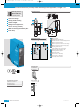
Sturdy plastic housing
Visible red light
Background suppression,
can be set very precisely
M16 screw fixing or equipment
plug rotatable by 90°
Test input, time delays and contami-
nation signaling output
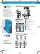
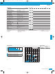
Dimensional drawing
WT 34 Photoelectric proximity switch with background suppression, red light – DC
Alignment sight
LED signal strength indicator
Standard direction of material being scanned
Middle of optic axis, sender
Middle of optic axis, receiver at close range
Middle of optic axis, receiver at long range
Mounting hole Ø 5.5 mm,
for M5 hexagon nuts on both sides
M16 screw fixing or
plug rotatable by 90°
Scanning distance adjuster
Light/dark selector
NPN/PNP selector
Time control t
2
= OFF-delay
Time control t
1
= ON-delay
Time delay selector switch
2
9
10
11
Q/Q
1
2
3
4
5
L+
M
Alarm
TE
1
L+
M
TE
3
brn
blu
4
Q/Q
blk
wht
2
1
L+
M
Alarm
TE
3
4
5
2
Q/Q
brn
blu
blk
gra
wht
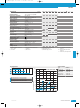
Connection type
M16, terminals 4-pin, M12 5-pin, M12
14
13
12
2
10
11
9
92
7027
6.2
73
5
max. 32
61.5
26.5
15
15.5
14
14
6.5
ø 5.5
30
10.5
4
2
1
6
7
5
3
8
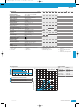
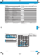
Adjustments possible
WT 34-V 250
WT 34-B 450
WT 34-V 240
WT 34-B 440
WT 34-V 540
14
13
12
11
10
9
8
7
6
5
4
3
2
1
WT 34-V 240
WT 34-V 250
WT 34-B 440
WT 34-B 450
WT 34-V 540
Scanning distance
100 to 1200 mm
Photoelectric proximity switch
See chapter Accessories
Cables and connectors
Mounting systems
Special accessories
KD01_W34_en.qxd 19.07.2006 15:33 Uhr Seite 876